Appearance
AI detection & review
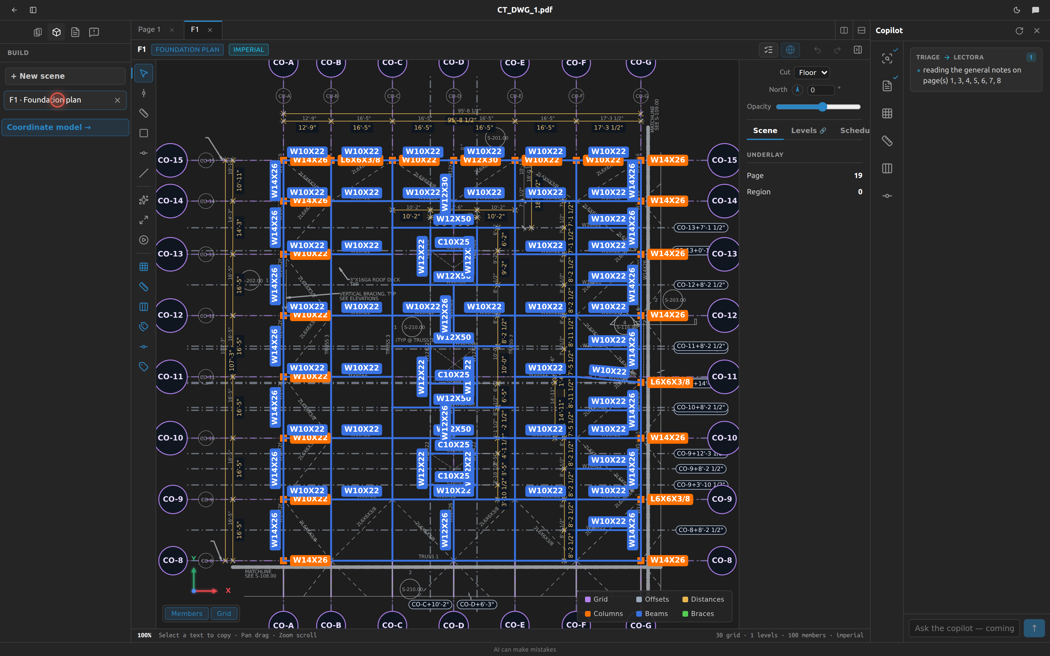
Fablnx can read a drawing for you — the grid, the scale, the columns, the beams and the sections written beside them — and it can carry steel across from the parts of the building you have already committed. This page covers every step, what each one needs before it will run, and how to check the result.
Before you start: nothing runs on its own
Detection is manual. There is no background pass, no queue, no "detecting…" that starts when you open a scene. You open a scene, you click a step, that step runs. Nothing chains into the next one.
Two things that do run on their own
Triage (identifying the structural sheets) and Lectora (reading the general notes) run automatically when you upload a drawing set. They are not scene detection — see The copilot.
Run a detect step
- Open the scene in the scene editor.
- Look at the bottom of the tool rail, below the separator under Fit view and Review. That group is the detect steps, in order.
- Click a step. Or right-click the canvas and pick it under the AI detect heading — it is the same list, in the same order.
- A badge appears in the middle of the canvas while it works: Detecting grid…, Calibrating…, Detecting columns…, Matching column profiles…, Detecting beams…, Matching beam profiles…, Prefilling from the building….
- Read the flash in the status bar when it finishes.
| Flash | What happened |
|---|---|
Detected 3 new items. (1 new item for one) | It added that many things to the scene. |
Detection ran — see the updated scene. | It ran and found nothing new. Not a failure. |
Detection failed. — or the server's own message | It could not run. The message says why. |
Two things to know about the buttons themselves:
- A plan shows the detect group only once it has a drawing underlay — a scene built on a page region. An elevation always shows it.
- While any step is running, every step is disabled. One at a time.
Your unsaved edits are flushed before a step runs, so you never detect against a stale scene.
The Run tab holds the working
Five steps show their reasoning: Detect grid lines, Calibrate, Detect columns, Detect beams and, on an elevation, Read members. Each writes its working into the inspector's Run tab, and the tab is always there — when nothing has been run it says which steps fill it.
- The tab opens on the step you just pressed. Run Calibrate with a grid run already in hand and the tab moves to Calibrate; the earlier run is still there, one click away on the switch at the top.
- Clicking the drawing does not take you off it. A run is read with the sheet — hover a crossing in the list to ring it on the drawing, click what it rings to inspect it — so selecting something leaves the Run tab where it is. Picking a tool does not take you off it either. Every other tab snaps to Props on both — which is what makes a click on a member show that member, and a tool you pick show its own panel instead of changing the cursor and nothing else.
- A run survives switching sheets. Open another scene tab and come back, and the run is still in the Run tab. It is dropped when you close it with the ✕ beside the switch, and closing it never removes what the run committed to the scene.
Detect a plan — seven steps, in this order
Each step is gated on the one before it. The gate is not a suggestion: the button is disabled, and its tooltip tells you exactly what is missing.
| # | Step | What it finds | Enabled once | Tooltip when locked |
|---|---|---|---|---|
| 1 | Detect grid lines | Every grid line the sheet draws, named from its bubble where there is one. | The scene sits on a sheet region. | — (a plan with no underlay hides the whole detect group, so this step is never shown locked) |
| 2 | Calibrate — read dimension ticks & bay distances, and every step it took | Dimension ticks and bay distances → the sheet's scale, plus the inspector's Run tab showing every step of the working. | There is at least one grid line. | Calibrate — detect the grid first |
| 3 | Detect columns — and what every crossing weighed | Columns at grid intersections, plus the inspector's Run tab showing what every crossing weighed and why one blob won. | At least one dimension is recorded. | Detect columns — calibrate first |
| 4 | Detect beams — every stage, and what each one weighed | Every beam the sheet draws, in stages run in order: the lineweight, column to column, curved, member to member, cantilevers, the infill the drawing never dimensions, and hanging members last. The chevron beside it runs one stage on its own. The infill stage creates grid lines, on the Offsets layer. | At least one column exists. | Detect beams — detect columns first |
| 5 | Detect braces and joists — dashed members between the steel already found | The dashed members that run between the steel already placed. After the beams, because a brace runs between beams and a joist frames between them. | At least one beam — detected or calculated — exists. | Detect braces and joists — detect beams first |
| 6 | Match profiles — choose columns, beams or braces | Asks which members to name — Columns, Beams, Braces, any mix — then reads the section written beside each member of those kinds, and, where Tekla already stands one at that station, the section the model carries. | At least one column, beam or brace exists. | Match profiles — detect columns, beams or braces first |
| 7 | Detect moment connections — the beam ends this sheet draws as fixed | The triangle a drafter puts where a beam meets its support: base across the end, apex where the member's ink stops. Each end is read as fixed, not fixed, or not yet looked at — three states, because a scene nobody has run this on must not look like one whose beams are all shear-connected. | At least one column and at least one beam exist. | Detect moment connections — detect columns first, or — detect beams first, whichever is actually missing |
Match profiles is one press now, not two. It used to sit between the columns and the beams, which meant naming a sheet twice — once for the columns, then again for everything framed after them. Below the braces, everything that can be named is already on the sheet.
Moment connections end the detection. A moment connection is a fact about a beam end, so every pass that can put a beam on the sheet has to have run first. Passes still to come will join it at the bottom for the same reason.
Below them, under a rule of its own, is Fill from the model — which is not detection at all.
Name only the members you choose
Match profiles writes a section only onto the kinds you tick, and leaves every other member exactly as it is. The callouts of the kinds you left out are still read, so a brace's size is never handed to the beam beside it just because braces weren't ticked. A kind with nothing on the sheet shows none on this sheet and can't be ticked.
One button, six stages, repeated until nothing new
Detect beams runs all six stages in the order they feed each other, and keeps going until nothing new turns up. Column to column is asked once — its pairs are the columns on the sheet, and nothing later adds one. Member to member and cantilevers then take turns until neither finds anything more, because each creates places the other can start from: a cantilever tip is somewhere a beam can frame into, and a beam's end is somewhere a cantilever can hang.
Only then does infill run. It is the widest net and the only stage that creates grid lines, so it goes after the stages that read a beam's own ink — that way a beam Fablnx can name from the line the drafter drew is always named that way. Anything infill places is an anchor, so the whole thing goes round again; it stops when infill adds nothing.
Curved sits with the straight stages rather than beside them: an arc between two crossings is still a beam the drafter drew, and asking for it separately would make it a second detector to keep in step with the first.
Hanging is last, and it is last for a reason. A member that stops part-way along another member has no second crossing to be named by, so what is true of it is an ADDRESS — that member, this far along — and every earlier stage's members are what it may hang from. Stored that way it moves when the steel carrying it moves, which is why these become calculated beams rather than beams pinned to an invented grid line.
Pressing the button twice will not find more than pressing it once. The chevron beside it takes a single stage, for when one floods or finds nothing and you want to look at it alone.
Anything it still misses is drawn with the Beam tool (B) or brought up from the model with Fill from the model. Everything downstream works either way: Match profiles, takeoff, validation and the 3D view do not care how a beam got there.
What the two profile steps can read
A callout is only recognised if it says something the step knows, and it knows two things at once: your project's schedules and the full AISC shapes catalog.
- Text that matches a mark —
C1,B12— is looked up in the schedule and the member gets the profile that mark stands for. - Text that matches a designation —
W14X90,HSS6X6X1/2— is taken as written, whether or not any schedule row carries it. - Where one text holds both, like
C1 HSS6X6X1/2, the mark wins — it is the one that resolves against your schedule.
So filling in the schedule is what makes marks readable, and it is never what limits you: a section the sheet calls out but no schedule row lists is still matched. Text that says neither is left alone, and a member no callout names keeps whatever profile it already had.
Matching is exact after case and spacing are ignored — HS6X6X1/2 does not match HSS6X6X1/2. A wrong section assigned silently is worse than none.
A callout counts as near a beam if it is near any part of the span, so a section written up at one end reads the same as one written at midspan. Each callout names at most one member and each member takes at most one callout, so two beams can never end up sharing a label.
What you name by hand, a re-run leaves alone
One callout, four beams — a plan writes W14x22 (4) once for the whole bay. The step gives that text to one of them, because a callout names one member; the rest you name yourself, by selecting each and clicking the same label (see Give every member a profile).
Run the step again and that work stands. A profile you set — clicked off the sheet or typed into the panel — is held out of the run: it is not re-read, not overwritten, and the callout it used is taken out of the pool before anything is matched, so it cannot be handed to a different member instead. Only the members Fablnx named itself are up for renaming, which is what lets it correct its own earlier answer without touching yours.
To hand one back, clear its profile. A member with no profile belongs to nobody, so the next run reads it like any other.
Detect an elevation — five steps
Detection does run on elevations. If you have read anywhere that it does not, that is out of date. An elevation gets its own five steps, worded for what an elevation actually shows, and the same Fill from the model group beneath them.
| # | Step | What it finds | Enabled once | Tooltip when locked |
|---|---|---|---|---|
| 1 | Detect grid lines & levels | The verticals and the horizontals, in one pass. | The scene sits on a sheet region. | Detect grid lines — place this scene on a sheet region first |
| 2 | Calibrate — read dimension ticks, bays and floor heights, and every step it took | Bay distances across, floor heights up, and this sheet's own vertical scale, plus the inspector's Run tab showing every step of the working. | There is at least one grid line. | Calibrate — detect the grid first |
| 3 | Detect levels — read the level marks & height callouts | The horizontal level lines on their own: level marks, flat-leader bubbles and EL callouts, each pinned to a project level. Step 1 writes these too; this is the standalone re-run. | The grid is in. | Detect levels — detect the grid first |
| 4 | Read members (2-Pair, offline) | Members read off the sheet's own geometry, landed on the grid × level lattice and named from the sheet. The chevron offers the other readers — two vision passes and, where the server has switched it on, astra. | The grid and its levels are in. | Read members — detect the grid & levels first |
| 5 | Name members from the sheet | Gives every unnamed member the section printed for it. Fills blanks only — a section a reader or a person already gave a member stays. | At least one member exists. | Name members from the sheet — read or place members first |
The readers under the Read members chevron are readings of the same job, not a sequence — run one, look at what it placed in the Run tab, and run another if you want a second opinion. The later one replaces the earlier: they are readings of one sheet, not halves of a population. Each shows the exact images it sent the model, the answer drawn on each, and what every member cost.
One detector, read two ways
Step 1 is not a second grid detector. It is the same one, and the elevation reads its answer differently: the verticals become grid lines, the horizontals become level lines. So one click gives you both families of datum on the sheet.
Calibrate works the same way — the tick engine answers in both axes at once. On a plan you only ever see the horizontal half. On an elevation both halves land: the horizontal strings name unnamed grid lines as usual, and the vertical strings name unnamed horizontals off the levels and measure the sheet's own vertical scale. That matters, because an elevation is often not drawn to the same scale up as it is across.
Calibrate only keeps a bay it is sure of
Calibrate only ever uses a number the drawing prints. A dimension string with no value written on it is not read at all — not as a bay, and not to work out where a grid line sits. Neither is one whose printed value the drawing's own geometry contradicts by more than 8%. The engine can measure the gap and guess what it probably says; the guess is thrown away.
That matters more than it sounds. Every grid line solves its real position from the chain of dimensions that reaches it, so a guessed distance does not just show a wrong number — it moves lines, and everything measured from them afterwards.
On top of that, each bay carries a confidence, shown in the dimension's panel as {n}% confident. Only bays above 80% are written. Above that line are bays where Calibrate measured the drawing itself and agreed with the printed number, and ones where it nearly agreed and the tick marks landed cleanly; below are values it could not check against a scale, or matched only because the number looked right.
A wrong bay is worse than a missing one. Every grid line downstream solves its real-world position from the chain of dimensions, so one bad bay silently rescales everything the chain reaches — and it looks exactly like a good one on screen. A bay Calibrate declines to write you can add yourself with the Dimension tool, and a hand-typed length reads Set by hand and is trusted completely.
Calibrate (Run tab) — watching it work it out
Run Calibrate and open the inspector's Run tab. Unlike the other panes, this one is a player: press ▶ and watch the run build the sheet's frame one dimension at a time.
It is a player because the order matters. Calibrate reads every printed dimension and solves where each line sits from the chain of them — and the first reading of a gap wins. If a weak dimension gets there first, the good one that arrives later is thrown out as a contradiction, and every line hanging off it is a few inches wrong from then on. A list of what happened cannot show that; watching it happen can.
Five sections:
Setup — what the run read off the sheet, the scale it settled on, and what each family of grid lines says the scale is on its own. Those numbers should agree; when they do not, the sheet's scale is a guess.
Dim lines — every dimension string and every span on it: what is printed, what it measures on paper, and what Calibrate decided to use.
Tick graph — the player, and the part worth your time. It shows the family's lines in the order they sit on the sheet, and against each one: the gap to its neighbour, and which dimension hooked it onto the chain and to which line. The line the chain started from is marked
first.Those last two columns can disagree, and that is the useful bit. A line placed by a long dimension reaching past three others leaves a gap beside it that nobody printed — Calibrate worked it out. When a distance looks wrong, that is usually where it came from.
It lights up the drawing too. The dimension it is working on — the line and its two tick slashes — is recoloured on the sheet itself, the same way a detected grid line or column is. Everything already applied stays faintly lit, so you watch the chain spread across the drawing as it plays: green where a dimension was accepted, red where it was thrown out as a contradiction.
Names — how each unnamed line got its name, like
D+9'-6 3/4": which grid line it was measured from and how far.Bays — every bay scored, and whether it cleared the 85% floor.
Amber means the same thing everywhere in the pane: Calibrate supplied this, the drawing did not. A span with nothing printed on it, a line it could not name, a bay below the floor. If a distance looks wrong, look for amber near it first.
Like the other debug panes, this is part of the run and not a saved report — reload and it is gone. Running Calibrate again brings it back, and commits exactly what the ordinary step commits.
How Read the beam lineweight works, and how to read it
Steel is drawn heavier than the grid, and everything a beam step will ever ask is asked at one line thickness. This step decides which, and lets you overrule it.
It looks for connectors: a stroke lying along a grid line with a detected column at each end. Nothing else votes — a stroke that runs from one column to another is the one thing on the sheet that is almost certainly a beam. Each connector votes its own thickness, weighted by its length, so a few long real members beat a crowd of short noise strokes, and the heaviest weight above the grid's own wins.
Open the inspector's Run tab and the vote is a slider:
- A stop for every weight the connectors voted, thinnest on the left. The stops are evenly spaced, not spaced by number, so every one is easy to hit.
- Drag it and that weight's ink lights up on the drawing. This is the point of the control. Whether a weight is the beam weight is not something a number tells you — you look at the sheet and see whether the members lit up are the members.
- Where it is left is what Fablnx uses. Let go and the weight is kept on the scene; every later beam step reads it. Clicking a row of the table below does the same thing.
- The table underneath is the evidence: how much total length and how many connectors voted each weight. A weight at or below the grid's own is marked
grid— the vote never picks one, though you may.
When nothing wins. If no weight beats the grid's own, Fablnx says so rather than falling back to the grid weight — a scene told its grid lines are beams would read the grid as steel. Pick a weight on the slider and it uses that instead.
When no connector is found at all, the sheet has no stroke running from one detected column to another. Detect columns first; if columns are there and this is still empty, the grid or the region outline is the thing to look at.
How the column-to-column stage works, and how to read it
Every pair of the scene's columns is asked one question: did the drafter draw a single line of the beam lineweight from one column face to the other.
Not only pairs that share a grid line — the ink is the evidence, and a member skewed across a stair opening runs along no line at all. A pair with a third column standing between them is skipped, because a member spanning past a column is two members.
One line, never a sum of pieces. Two unrelated fragments end to end will add up to any threshold you care to set, so a bay is only a member when a single line runs it. Pieces of one line are still one line: where a drafter trimmed and redrew, or extended one line over another so they overlap, the pieces are joined before the question is asked — provided the gap is tiny next to the pieces themselves. A dashed member's gaps are about half the length of its own dashes, so dashes are never welded into a solid line.
Face to face, not work point to work point. A beam stops at the column face, and the column's own drawn outline is what says where that is.
Open the inspector's Run tab and the 1 · Column to column section lists every pair:
- The two crossings, by name —
A × 2 → A × 3. - How much of the bay the longest single line covers, as a bar. Not the test, but it separates a member with a small connection gap at each end from a stub that stops halfway.
- Why it was passed over, when it was: no ink (nothing at the beam lineweight runs between them — check Read the beam lineweight on the chevron), not one line (there is ink along the bay and no single line spans it — a dashed member, or two members it is right not to weld into one), touching (the two columns meet, so there is no gap to draw a member in), or column between.
Most pairs on a floor have nothing drawn between them — a 68-column plan examines about two thousand pairs and keeps sixty-odd — so filter with all / kept / passed over.
The drawing follows. Members placed are green; hover a row and that pair is drawn thick with both ends ringed, blue if it was taken and a red dash if it was not. Tick draw the passed-over pairs to see every bay the run looked at and declined, which is the quickest way to find a beam that is on the paper and not in the model.
Like the other debug panes, this is part of the run and not a saved report — reload and it is gone. Running it again brings it back, and commits exactly what the ordinary step commits.
Running it again never deletes a beam
A re-run adds what is new, and where it finds a member at a place that already holds one — one you drew, one inherited from another floor, one an earlier run placed — it takes that row over rather than stacking a second beam on it. The row keeps its profile and its mark. Nothing is removed for not being found: a run that reads the drawing differently is not a reason to delete steel you are relying on.
One case it cannot recognise: a beam you drew whose ends are not grid crossings has no crossing pair to match on, so a detected member across the same bay will sit alongside it.
How the member-to-member stage works
The first stage finds the frame: the members that span column to column. On a real floor that is the minority of the steel — most beams land part-way along a girder, at a place the column-to-column stage never asks about, because it only knows where the columns are.
The second stage is the same question one step further out. It walks every crossing that already carries steel — one a member stands at or passes through — and asks every pair of them whether a single line of the beam lineweight runs between them. A girder from A×1 to A×5 passes through A×2, A×3 and A×4 on its way, and each of those is a place its own infill hangs off.
The pair does not have to sit on a grid line. A member framing between two girders at an angle to the grid, or between two offset stations on different lines, is drawn like any other member, and this stage asks about it like any other pair. Both ends are still grid crossings — that is how a member is named and how the same piece of steel is recognised on the next sheet.
Pairs with nothing drawn between them are passed over before they are asked about. On a busy sheet there are hundreds of thousands of pairs of crossings, and almost all of them are lines the drafter never drew. Fablnx checks whether ink of the beam lineweight runs along a pair at its middle, and only then does the full reading — so a dense floor plan takes seconds rather than minutes. Nothing that would have been found is skipped: a member's line has to run the whole way between its ends, so it is always there in the middle.
It repeats until a pass finds nothing new, because every member it places carries more crossings for the next pass to start from. The pane reports how many passes it took.
It walks from whatever the scene holds — what the earlier stages just found, what you drew by hand, what came up from another floor. Draw a beam the detector was missing, press Detect beams again, and it frames into that beam like any other.
A member already found is not found again. Once a crossing a girder merely passes through can be asked about, the only line spanning that sub-bay is often the girder itself — so a girder would be read as every sub-bay of itself. Fablnx knows which strokes each beam is drawn with, and a bay whose only line is ink already spoken for is passed over as same ink. On one plan that is the difference between 29 real members and 140.
The Run tab lists every pair, kept or passed over, exactly as the column-to-column stage does. Two reasons are particular to this step: same ink, and too short — a bay shorter than the uncertainty about where its own ends are is not asked about at all.
How the cantilever stage works
A cantilever has steel at one end and nothing at the other, so the first two stages cannot see it — both need support at both ends. The cantilever stage asks the same question with one end let go: a crossing that already carries steel, and the empty crossing next to it along a grid line.
The line has to stop at the free end. If the ink carries on past it, the member carries on to somewhere else and this is the wrong pair — that bay is passed over as runs past. Without this rule every crossing a long beam passes over would become a cantilever tip: on one plan it is the difference between 6 cantilevers and 26.
A free end stops being free the moment something lands on it, so two halves of one run can never come back as two cantilevers hanging off each other.
What "free" means here
Free of what Fablnx has found — not unsupported in the real frame. A beam that carries on through a connection drawn at a lineweight this step does not read looks free to it, and will be offered as a cantilever. Check the ones it finds against the drawing.
A cantilever's tip counts as support from then on, so running member to member again afterwards can find beams framing into it.
How the infill stage works, and the grid lines it creates
An infill beam has no grid line through it and no dimension to it — that is the whole point of writing EQ, TYP or UNO on a drawing. Every other step finds a member by its ends landing on grid crossings, so every other step is blind to these.
This one works the other way round: it reads the ink first. Every line at the beam lineweight that no member already accounts for, whose two ends land on two different members already placed. A line landing on nothing is loose; on one member only, one end; on the same member twice, one anchor; and on a member running the same way as the line itself, parallel anchor — an end is where two lines cross, and two parallel lines never do.
It creates grid lines, and that is deliberate
An infill beam stands on a line the drawing never drew, and Fablnx stores a beam end as a pair of grid lines — so the line has to exist before the beam can. This step mints one for each, at the beam's own measured position, named the way an offset line from calibration is (A+12'-5 15/16"), and it appears with your other offsets on the Offsets layer.
The pane tells you how many lines a run created. A line named this way is the same name calibration would give the same place, so finding it twice can never make two lines.
Where the beam is put. At the position it is drawn at, not at an exact division of the bay. A run of one is common and dividing a bay proves nothing about it. The trade is that a drawing which really does say EQ is recorded a fraction of an inch off its own intent rather than snapped to perfect fifths.
When a line cannot be named. Naming an offset needs the grid labels to agree which side of a line counts as forward. When they do not, the step reports no name and places nothing, rather than putting the line on the wrong side of its anchor.
This step depends on the three before it more than they depend on each other — it frames into what they placed, so on a floor where little was found it finds little.
Why there is no Detect columns on an elevation
The member detectors are written for a plan. A plan anchors a member to two grid lines; an elevation anchors it to one grid line and a height. Pointing the column detector at an elevation would write a column at two grid lines, where the second one should have been a level — plan-shaped rows in a sheet that cannot hold them.
So it is refused rather than half-done. Trace the members with the Member tool (see Tracing an elevation), or bring them in with Prefill from the building, which reads the Tekla model and does not care which view you are in.
When prefill is locked
Fill from the model has the longest gate of any step, because it needs both a scene worth writing into and a building worth reading from. The reasons arrive in order — clear one and the next may appear.
On a plan:
| Order | Reason shown | What to do |
|---|---|---|
| 1 | connect to tekla first | Open the model in Tekla. Prefill reads the building, and the building lives there. |
| 2 | add a dimension (calibrate) first | Record a dimension, or run Calibrate. |
| 3 | give this scene a level first | Set the scene's level. |
| 4 | tekla holds nothing at or below this level to inherit from | Push a sheet at or below this one into Tekla. Prefill reads the model, so steel has to be standing in it. |
On an elevation:
| Order | Reason shown | What to do |
|---|---|---|
| 1 | pin a level first (level tool, l) | Pin a level with the Level line tool (L). |
| 2 | push a sheet into Tekla first | Push any sheet. Prefill reads the model, and the model is empty. |
The reason is printed in lower case
The tooltip lower-cases the whole reason, so you will read Fill from the model — pin a level first (level tool, l) — with a lower-case level tool and a lower-case l for the key. It means the Level line tool and the L key.
What detection can and cannot reach
Every member Fablnx places is anchored to a grid intersection. That is what lets the same piece of steel be recognised on the next sheet, and it is also the limit:
- Detect beams reaches column to column, member to member, cantilevers and infill. A beam still has to run between two places the model can name: one framing into the middle of a girder with nothing at its far end, or a cantilever whose tip lands at no crossing, is a place the model cannot refer to. Draw those yourself.
- Detect columns deliberately errs toward showing you too much. It offers every distinct shape it sees, including ones that appear only once, so expect the occasional piece of detail ink among the real columns. What it will not offer you is something far too small to be a column — a bolt or an anchor rod — or something sitting off to the side of the crossing rather than on it. Both grid lines have to run through a shape before it counts.
- A grid line counts everywhere it goes, not only where it is drawn. Columns are looked for at every crossing of the grid inside your region outline, including crossings past the end of the dash-dot line on the sheet. Draftsmen routinely stop a grid line short of the last bay, and the columns out there are still columns. It also means shortening or extending a grid line in the editor does not change what detection finds — only moving it does.
Review the result and delete what does not belong. That is the workflow, and Review detections is the fastest way through it — though note it walks everything in the scene, not only what detection added.
Why it over-offers rather than under-offers
A column it showed you and you deleted costs one keystroke. A column it quietly skipped costs you a piece of steel missing from the model, and you will not find out until something further down the line asks for it. Deleting is cheap; noticing an absence is not. So the detectors are tuned to be shown and corrected, not trusted blindly.
There are no switches under the detect steps
A Detect columns run has no modes. There is nothing to arm beforehand and nothing to remember to put back — every run behaves the same way, so a result can be compared with the one before it.
The shape check always runs. The vision model that looks at each distinct shape and removes the ones that are not sections used to have an eye toggle in the rail; it does not any more. The only time a run goes without it is when the model cannot be reached, which is not a setting and which the run tells you about — see When the shape check is unavailable below.
The One lineweight funnel that used to sit beside it is gone too, and so is the lineweight vote that replaced it. Every pass now looks at every line thickness — see below.
Three passes, most certain first
Your grid is not one kind of line. Some are named: the ones the drafter bubbled and lettered — A, 3, C.5. The rest are work points the tools derived off those, labelled things like C.5+4'-0 1/2" — that label is our sentence about the sheet, not something written on it.
A column standing where two named lines cross is about as sure a thing as a drawing offers. A "column" found where two derived work points cross is a much weaker claim. So Detect columns works down that order:
| crossings it searches | how strong the claim is | |
|---|---|---|
| pass 1 | named × named | as sure as a drawing offers |
| pass 2 | named × unnamed | one end is a work point we derived |
| pass 3 | unnamed × unnamed | both ends are |
Every pass looks at every line thickness. Pass 1 used to vote one column weight and filter the rest of the run by it, and that has been removed: a sheet that draws its steel at two weights lost the second one along with the detail. On one measured floor plan that was four real columns, standing at named crossings, in shapes of their own. The shape gallery and the shape model are what separate steel from detail now.
Each pass spends the ink it uses. Once a column is placed, the exact linework it was made of is withheld from the passes after it, so the same steel is not found a second time at a work point a few inches away. On one measured sheet this removed 15 duplicate columns.
The result line names the passes: "79 detected … — passes 67/7/5".
You will see more to review
Nothing filters a candidate out for being drawn at an unusual weight any more, so detail ink drawn like a section reaches the shape model rather than being stopped before it. Read the gallery — real sections come out as a few tiles with high counts, detail as a tail of one-offs.
What this can get wrong. Spending the ink cannot tell "the same column seen twice" from "two columns that share one polyline". On the sheet measured, that cost exactly one real column out of 79. If a column is missing and you suspect this, open Detect columns (debug) and look at its crossing: it will show no candidates at all, which means its linework was already claimed elsewhere. :::
The shape gallery in the Run tab
When Detect columns finishes, the inspector's Run tab shows a thumbnail of every distinct shape it kept, captioned with the line weight, how many of that shape were placed, and how closely they matched each other. That is the fastest way to tell real sections from detail ink: the sections come out as a few tiles with high counts, and the tail is usually one-offs. It also shows what the run threw away, so you can see both halves of the decision.
Every shape is shown, so a busy sheet arrives as several images in a row — Column shapes (1/5), (2/5) and so on. Nothing is left out of the picture.
The gallery is part of the run, not a saved report: reload the page and it is gone, and the only way back to it is to run Detect columns again.
Detect columns (debug) — why this one, here?
The gallery answers columns, or anchor bolts? for the whole sheet. It cannot answer "why is there no column at C×4, when I can see one?" — and that is the question you actually have when something is missing.
The microscope step in the detect group runs the columns detector and commits its results exactly as the ordinary step does, then opens the Run tab in the inspector on the right showing what it weighed. It costs a little more time and nothing else; the rows it writes are the same rows.
The tab appears while a run is in hand and goes away when you close it. Detect grid lines fills the same tab with its own account — of every circle on the sheet, why it did or did not become a grid line — so with both runs open the tab carries a Grid / Columns switch at the top.
Every crossing it searched is drawn on the drawing, as a ring around the point it searched (drawn half again as big as the real window, so it can be seen and pointed at):
| green | a column was placed here, in pass 1 — two named grid lines |
| blue | placed in pass 2 — one named line, one work point |
| violet | placed in pass 3 — two work points, the weakest claim |
| red | ink was weighed here and all of it was thrown away |
| grey, dashed | searched, and nothing thicker than the grid line was inside |
There are a lot of these — a dense scene searches thousands of crossings and about four in five held no candidate ink at all. The button in the pane header cycles what is drawn:
| only crossings that weighed something (default) | the few hundred that decided anything |
| every crossing searched | the empties too — turn this on when your question is about a crossing that came up empty |
| hidden | nothing but the one you are hovering |
The pane's top line always says how many are hidden, so you are never quietly missing some.
The column itself takes the same colour. Not just the ring — the steel drawn on the sheet is recoloured green, blue or violet by the pass that placed it, so you can read a whole region at a glance and see which columns rest on the weakest evidence. A column in its ordinary colour is one this run did not place: hand-drawn, or inherited from another scene.
The grey ones are the point. If the crossing you are asking about is grey, no candidate ever existed there — the column is drawn at the grid weight or lighter, it sits outside the ring, or its linework was already spent by an earlier pass. If it is red, something was found and rejected, and the pane says by what. The three placed colours are the three passes — see Three passes, most certain first above — worth a look before you trust a violet one as far as a green one.
Hover a crossing. Every piece of ink that reached it is painted where it is, coloured by what became of it — and this is the layer to read first, because it is the whole population. The blob list below it only ever speaks about ink that survived long enough to be grouped into a shape.
| green | placed, or part of the blob that was |
| amber | a real candidate that got beaten |
| violet | touches the circle but is not fully inside it |
| grey, thin | at or under the grid line's weight, or not a polyline — never steel |
| blue, thin | already placed as part of a column at an earlier crossing |
If a crossing you can see a column at came up empty, this is where the answer is. The pane lists the same breakdown with counts.
Then the blobs — the ink that got as far as being grouped into a shape. The pane splits them in two, at the split that matters:
- reached the closest-to-centre contest — every one of these sat inside the ring, at its own thickness, column-sized, with a corner, and with both grid lines running through it. Distance to the centre alone chose between them, and the winner is marked. When the wrong shape was picked, the right one is in this list.
- never reached it — stopped by a gate before distance was ever compared.
Each blob shows a thumbnail, the line weight, the distance, and a sentence for what stopped it:
- smaller than a column on both sides — a bolt, a tick or a hatch cell
- one lone segment — no blob / a straight line, no corner — not an outline
- a grid line does not pass through it — a column stands on the crossing, so both grid lines have to run through its outline
- a circle centred somewhere else — a bubble clipping the crossing, not a round column
- another blob at this crossing was closer to the centre — it was a fine candidate and something better won. This is the one to look at when the wrong shape was picked.
- the vision model called this shape noise — read the prompt and the picture it was sent in the debug pane before deciding it got this wrong
- the same steel, claimed twice — an overlap with a nearer blob
What the model was shown. The pane carries the exact picture sent for each distinct shape, which is not the gallery thumbnail — it is the shape with its grid lines drawn through it in colour, because the model is asked one question covering three things at once: is this a section, and if it is an I, which coloured line does its web run along and at what angle to that line. One request, one line back per image. The label, colour and angle it answered sit under each picture, and the prompt is one click away — worth reading before deciding the model got something wrong, since "Noise" means whatever the prompt says it means.
A picture the model approved that went anyway names the filter that took it, rather than saying only that something did:
| It says | What removed the shape |
|---|---|
| dropped: the same steel, claimed twice | Two candidates covering one piece of steel |
| dropped: another blob sat closer to the centre | It lost the closest-to-centre contest |
| dropped: another crossing owns this ink | A neighbouring crossing had already claimed it |
These are the ones to look at when a column you expected is missing but the shape looks right. Naming the filter matters most when the model answered for nothing at all: every shape then reaches this branch, and "removed after the model" would credit a silence with the filtering.
A picture marked no answer · kept is one no verdict came back for. It is not a verdict and it does not remove anything — a shape that could not be read is not a shape anyone said to drop, so it stays.
The crossings are listed too, most candidates first, each with a thumbnail of what it placed (or of its best candidate if it placed nothing). Hovering a chip is the same as hovering the crossing on the drawing.
The crossing and the gallery point at each other. Hovering a crossing rings the gallery tile its winner became, so you can see what shape was placed without hunting for it. Clicking a tile does the reverse and rings every crossing that became that shape — the fastest way to check whether one shape was placed somewhere it should not have been.
Like the gallery, it is part of the run: closing the pane or reloading drops it, and the committed columns stay.
When the shape check is unavailable
After the geometry has picked out the candidate shapes, a vision model looks at each distinct one and says whether it is a section or just detail ink. If it cannot be reached, detection still runs and keeps everything — the model only ever removes shapes, so without it you get more to review, never less. The Columns card says so on the result line ("shapes not vetted"), so you know to look a little harder at that run.
This is the only way a run goes without the check. It is not something you can choose — there is no switch for it, and a run that says "shapes not vetted" is telling you the model was unreachable, not that anyone turned anything off.
The debug pane says so too, at the top of what the model was shown: "N images were built, and no model answered for any of them." Worth knowing, because such a run does not look unusual otherwise — every shape the geometry proposed is placed, at no rotation, and a full-looking result is exactly what an unvetted run produces.
What detected work looks like
On a plan, detected steel is the drawing itself, in colour. Nothing is drawn on top of the sheet:
- a column shows as the actual section — its flanges and web, or its box outline;
- a grid line shows as the rule the drawing runs;
- a beam shows as the line it was read from;
- where a grid line has a bubble, the drawing's own bubble takes the colour and the letter inside it turns with it. There is no second bubble printed over the real one.
The colour follows exactly the part of the sheet that was read, not the whole stroke it belongs to. A grid rule drawn as one long dash-dot line across the page lights up only where the detector actually traced it; the rest of that same line stays grey with the drawing. So the colour tells you what Fablnx recognised, rather than how the drawing happens to be split into strokes.
Anything you placed is drawn in the plain style instead — a square at the intersection for a column, a straight line for a beam, a dashed rule for a grid line. So are members brought in by Fill from the model, since those were never read off this sheet.
The two styles are the answer to "where did this come from?"
Coloured sheet linework means this drawing says so. Plain Fablnx linework means you drew it, or the building next door did. You can tell at a glance, without opening a panel.
Only named grid lines take the sheet's own ink — an offset line has no drawn rule of its own to recolour. And on an elevation only the grid lines come back this way, so elevation members always draw in the plain style.
The colour stops where the reading stops
A drawn shape can be one long path — a detail boundary with ten corners, a callout bubble, a table edge — and only part of it may be what a grid line was read from. Only that part takes the colour; the rest stays drawing.
This is worth knowing because it used to work the other way. A grid line that ran along one straight stretch of a big shape coloured the whole shape, so a detail bubble touching a grid line lit up as though it were the grid. If you remember seeing that, it is fixed — and if you see it again, the colour is telling you something real about what was read.
Where a section comes from
A member can get its section from two places, and they are not equal.
| Source | What it is | Beats |
|---|---|---|
| The building | Tekla already stands a member at that station, and it carries a section. | The page's callout. |
| The page | The nearest section text on this sheet, matched to the member. | Nothing — it is the fallback. |
The building wins because it may hold something you corrected by hand in Tekla, and a callout on the drawing cannot know about that. It is also the only answer available on a sheet that never prints a section: column sizes are usually scheduled once, on the lower plan, so the sheet for level 3 draws its columns and names none of them.
The building means Tekla, and only Tekla
Your other drawings do not count. A section another sheet was traced with is a reading of a drawing, not the building — it used to win here, which meant a traced sheet could quietly override a correction someone had made in the model.
So with no Tekla connected, or nothing pushed yet, the building states nothing and the page's own callouts stand alone — exactly as they always did. Detection still runs in the browser; it just has one fewer opinion to weigh.
A section you typed by hand is never overwritten, by either source.
Section callouts
Where the sheet writes a section beside a member — W14X90 next to its column — that text takes the member's colour, and a dotted leader in the same colour runs from the member to it. Fablnx does not print its own chip over it, so you can see which callout belongs to which piece.
- A member the sheet does not name — one you placed, one prefilled — still gets a plain chip.
- The highlight appears only after
Match profileshas run on that scene. It is recorded while the sections are being read. - A column with no section assigned still gets its red ring and a
no profilechip.
Edit a profile to something the drawing does not say there and the link lets go. The callout stops being highlighted, the leader disappears, and you get the plain chip back — because the sheet no longer names that member. Set it back to what the drawing says and the highlight returns.
What does not count as a change:
- capitalisation;
- spacing;
- a leading mark alongside the section, like
C1 HSS6X6X1/2.
Two practical notes
Zoom in to read a section. A column section is genuinely small at full-sheet zoom, so a plan zoomed out shows the steel as specks.
Click a column's centre, not its flange edge. Clicking still targets the grid intersection, not the drawn outline — so if a column will not select when you are zoomed right in, aim at the middle.
Fill from the model
The last thing on the rail, under a rule of its own, because nothing in it reads this sheet. Everything here arrives from somewhere that already knows it: the Tekla model, a sheet you have already committed, or a schedule.
The button does the one thing it is named for — it reads the model. The chevron beside it opens the rest:
| In the menu | Brings | From |
|---|---|---|
| Everything the building knows | Members, with profile, grade and orientation. What the button itself does. | Your Tekla model |
| Import statements | Labels and distances in feet about the grid lines this sheet draws — statements, not geometry. | Sheets of this project you have committed |
| Copy grid lines from a committed sheet | The grid LINES themselves, for a sheet that draws none of its own, fitted through the rings both sheets draw. | One committed sheet, which you choose |
| Bays between grid lines | The distances between grid lines. | Scenes already committed |
| Column profiles from the schedule (plan only) | The section at each column, by grid intersection rather than by matching text. | A schedule drawn as an elevation |
Import statements and Copy grid lines used to be buttons of their own, up beside Calibrate. They are the same idea as the rest of this menu — rows this sheet does not draw, arriving from somewhere that already holds them — and as top-level buttons they were two of the four things you met before detecting anything.
Some things a drawing simply does not say. Column sections are usually scheduled once, on the lower plan, so the sheet for level 3 draws the columns but never names their size — and no amount of detecting that sheet will find one.
Fill from the model fills them in from the building — and the building is your Tekla model.
| What arrives | From where | Bringing |
|---|---|---|
| Columns | Steel standing on the nearest level below. | Profile, grade and orientation. |
| Beams and braces | Steel standing at the same level — or, on a sloped roof or deck, on the slope that rises from it. | Profile and grade, and the height of each grid line the slope crosses. |
It reads Tekla, not your other sheets
Prefill used to read the project's other drawings as well. It does not any more: a sheet someone traced is a reading of a drawing, and the model is the building. That matters most when the two disagree — a section you corrected by hand in Tekla is the one the next sheet inherits, where before a traced sheet could quietly override it.
The cost is that a job with nothing pushed prefills nothing, and says so rather than filling the sheet in from itself. Push a plan and prefill has something to carry across.
A member only arrives if this scene's grid has the lines it sits on. Fablnx matches by grid label and level — it turns each piece of steel's position in the model into the pair of grid lines it stands on, so 2 × B in Tekla is 2 × B on your sheet, whatever the sheet's scale is. Steel standing nowhere your grid names, or at a height none of your levels names, is left out rather than guessed at.
A sloped roof fills its own slope
On a roof or deck that slopes, the beams and braces are not at the plan's level — they rise off it. Prefill follows them up: starting from the steel at the plan's level, each beam that climbs to the next grid line tells that line its height, and the next beam carries on from there. A grid line that only a beam running along it stands on gets the height Fill slope would give it, and only if the beam in Tekla is at that height.
So you do not have to Fill slope before prefilling a sloped plan. The grid lines' heights arrive with the steel, in the same step, and you can check them in the grid table. A height you already gave a line is kept, and steel that disagrees with it is left out. So is steel on another floor, and anything the model does not make clear, like two beams putting one line at two heights.
Each intersection finds its own floor below
There is no single "floor below" for the whole scene. Every intersection settles it separately: the nearest level beneath this one that actually stands a column there.
That matters when a level is split into areas. ROOF FRAMING PLAN — AREA B takes what stands under Area B — not what stands under Area A, just because Area A happens to sit at a higher elevation. Areas that do not reach your grid lines simply do not contribute.
Prefilled members are ordinary content
Edit them, delete the ones that do not belong, undo the run. They are scene content like anything else — nothing about them is locked.
Last run wins
You can run prefill before or after the detect steps, and as often as you like.
- Where two runs claim the same intersection, whichever you ran last is what stands.
- Everywhere else, they add up.
- Prefill unseats your own hand-placed member at an intersection it claims — the floor below is where the section is written down, so it gets the last word there.
- The sheet detectors never touch your own work. Re-reading a drawing is not grounds to delete something a person placed.
- Members anywhere a run did not reach stay exactly as they are.
When frames disagree
An elevation can name more than one grid line — ELEVATION ALONG GRIDS B, C, D, F, G, H & I — and that is an assertion: those frames are identical.
If the model disagrees, prefill stops and writes nothing. A modal opens:
These frames are not identical
Each row tells you:
- which member it is (column, beam, brace);
- where — at which grid and at which height;
- which of your grids have it and which do not, or the two sections it found, joined by
vs; said by— a button per committed scene that says so. Click one and that scene opens, so you can go and look.
The fix line reads: Narrow this scene to the grid lines that match, or split it in two — then prefill again. The only button is Close.
Why nothing is written
There is deliberately no "do it anyway". A half-filled elevation is worse than an empty one: it looks traced, while quietly missing steel on some of the frames it claims to stand for. You would have no way to tell which frames got the full picture and which did not.
Stopping means the scene is still honest — it says nothing rather than saying something for some grids only. Narrow the grid lines to the ones that genuinely match, or split the scene in two, and run it again.
Review what was detected
Detection is meant to be checked. Review detections is an auto-play tour: it builds an ordered list of everything in the scene — grid lines, offsets, dimensions and members, whether detection found them, prefill brought them in, or you placed them yourself — and steps through it one item at a time, flying the canvas to each so it is centred and in context, highlighting it, and selecting it — so the inspector shows the thing under review and you can correct it rather than only accept or delete it.
- Click the play button in the tool rail, below Fit view.
- On a plan its tooltip reads
Review detections — auto-play & verify. - On an elevation the same button reads
Review this sheet — auto-play & verify.
- On a plan its tooltip reads
- The review HUD appears at the bottom of the canvas. It plays on its own and stops at the end.
- Fix, delete or skip each item.
- Press Esc to leave.
| Control | Tooltip | What it does |
|---|---|---|
| Grip | Drag to move | Drags the HUD anywhere inside the canvas. Park it out of your way. |
| Close | Exit review (Esc) | Leaves the tour and drops the selection it drove. |
| Counter | — | {n} / {total}, with a progress bar. |
Scope: All | — | Tours everything. |
| Scope: category | — | Grid, Offset, Dist, Col, Beam, Brace, each with its count. Only categories actually present are offered; clicking one jumps to its first item. |
Follow | Not following — the review selects each stop and leaves your view alone. | Whether each stop frames its member in the Tekla model, or only selects it. Off to start with, and shared with the model checker and the connection tour — turn it off in one and it is off in all three. |
| Where | Walk only what is in front of you | Narrows the tour to one level, one grid line or what you had selected when you pressed play. Whole sheet is everything. Each choice carries its count, and only the ones this sheet can offer appear. |
Start over | — | Shown only when the tour resumed. Restarts from the first item and forgets the bookmark. |
| Previous | Previous (←) | Step back. |
| Play / Pause | Play / Pause (Space) | Auto-advance on or off. |
| Next | Next (→) | Step forward. |
| Speed | — | ×0.5, ×1, ×2. |
Remove | Remove (R / Del) | Deletes the current item — a member, a grid line or a dimension. The list shrinks and the tour carries on. |
Keyboard while the tour is open: Space play/pause, → next, ← previous, R / Delete / Backspace remove, Esc exit. These win over the editor's own shortcuts while the tour is running, and are ignored while you are typing in a field.
Reaching into the inspector pauses the clock
Click into the properties panel to fix a profile and the auto-advance stops on its own. There is no button for it — it just waits for you.
It resumes where it stopped
A pass over four hundred members is not one sitting. Fablnx remembers the stop you left each sheet on, and the play button says so: Resume the review at 128/412 — B·3. Pressing it opens the tour on that stop, paused, with the scope you were using, and the HUD offers Start over if you would rather begin again. Finishing a pass forgets the bookmark.
The stop is remembered by what it was, not by its position — so re-detecting a sheet or deleting members does not resume you onto the wrong item. If the thing you stopped on is gone, the review simply starts from the top.
It is kept in this browser, per project and per sheet, and it is not part of the project: another machine starts fresh.
The review plays in Tekla too
Running inside Tekla Structures, each stop on a member also selects that member in the open model — so the tour walks the actual steel rather than a picture of it, and you can look at both windows at once.
It selects only, unless you ask otherwise. Framing somebody's view every second and a half while they are mid-edit is the one thing that would make it intolerable, so the Tekla camera is left alone until you turn Follow on in the HUD.
Detection and the copilot panel
The copilot panel reports on Triage and Lectora, the two stages that run when you upload a set. Detection is not one of them.
Watch the scene instead: the busy badge on the canvas while a step runs, the status-bar flash when it finishes, and the inspector's Run tab for what the run actually weighed.
Where to go next
- Tracing a plan — placing what detection did not reach.
- Tracing an elevation — levels, offsets, slants and the Member tool.
- Validation & the world — checking the scene and committing it, which is what makes it available to prefill.