Appearance
Tracing a plan
This page is the whole job, start to finish: taking a framing plan and turning it into steel Fablnx can model. It assumes you already have a scene open — if not, see the scene editor for creating one and finding your way around the canvas.
Everything here is for a plan. An elevation locates steel differently and has its own tools — see Tracing an elevation. If you would rather let the copilot do the first pass and review its work, see AI detection; the order below is the same either way.
The order of work
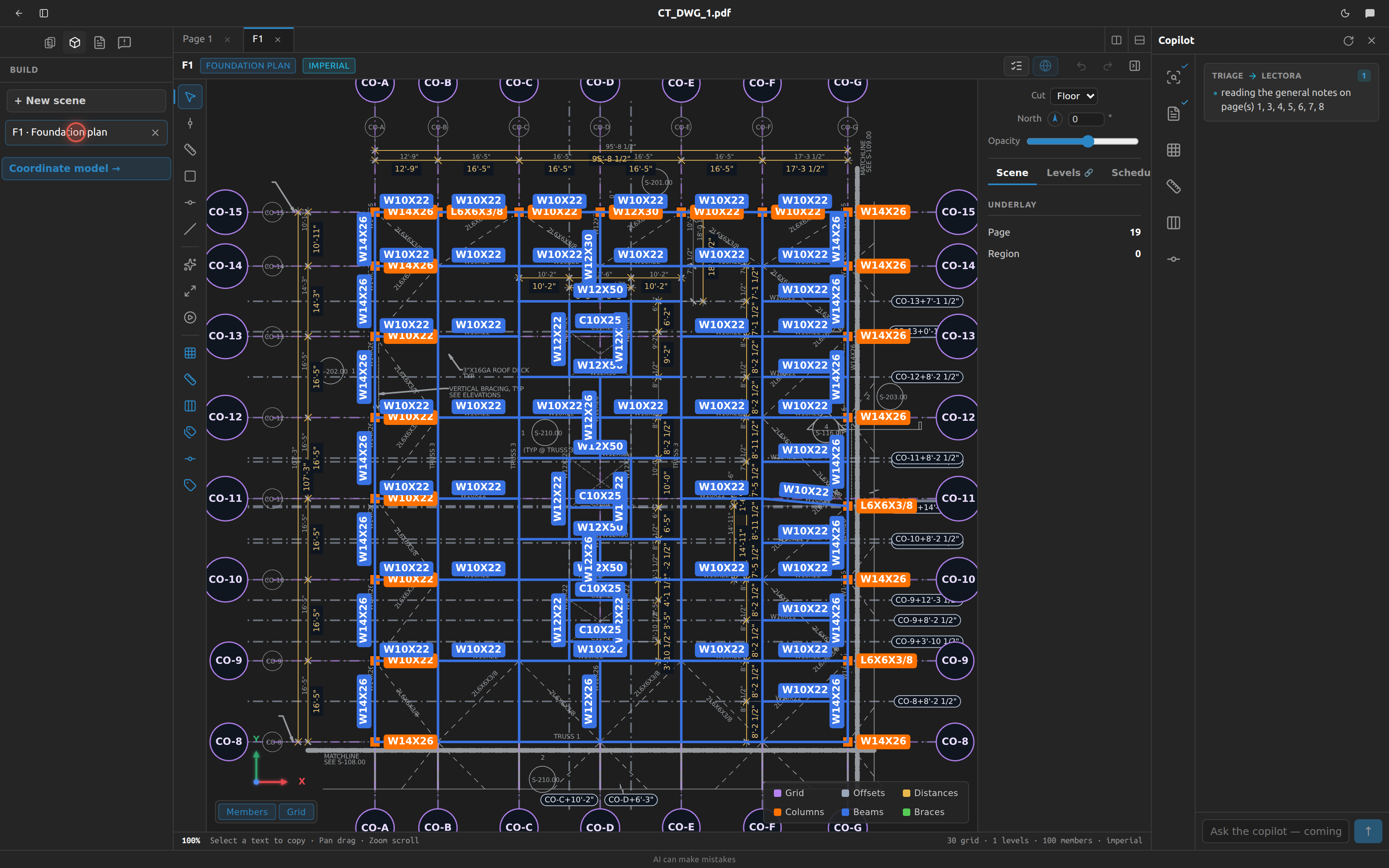
The tools unlock in sequence. Each one needs the step before it, so the rail tells you where you are: a locked tool is at 35 % opacity, can't be clicked, and its tooltip names what is missing.
| # | Step | Tool | Key | Unlocked once |
|---|---|---|---|---|
| 1 | Place the grid lines | Grid line | G | always available |
| 2 | Name them from the bubbles | Grid line | G | always available |
| 3 | Record a dimension | Dimension | K | there is at least one grid line |
| 4 | Place the columns | Column | C | there is at least one recorded dimension |
| 5 | Give every column a profile | Column | C | — |
| 6 | Place the beams | Beam | B | there is a column, and every column has a profile |
| 7 | Place the braces | Brace | X | same as beams |
The exact locked tooltips, so you can match them on screen:
| Tool | Tooltip when locked |
|---|---|
| Dimension | Dimension — two grid lines + a distance — Draw grid lines first |
| Column | Column — one grid intersection — Add a dimension (Calibrate) first |
| Beam | Beam — two grid intersections — Place columns first |
| Beam | Beam — two grid intersections — Give every column a profile first |
| Brace | Brace — two grid intersections — Place columns first |
| Brace | Brace — two grid intersections — Give every column a profile first |
TIP
If the tool you are holding becomes locked — you deleted the last dimension while the Column tool was active — the editor drops you back to Select rather than leaving you with a dead cursor. Pressing a locked tool's hotkey does nothing.
Why the order is forced
Every member is anchored to a grid intersection, so there is nothing to place a column on until the grid exists. A column's position is only a position in feet once a dimension says how far apart two lines are. And a beam is described by the columns it frames between — the section sizes on the plan belong to the columns first, which is why the beam tool waits for them.
1. Place the grid lines
- Press G for Grid line. The tooltip reads
Grid line — click a drawing line or its marker. - Click a grid line on the drawing, or click its bubble marker. Fablnx picks up the whole straight run of that line, not just the segment you clicked.
- Repeat for every line in both directions.
A click that lands more than about 12 px from a drawn line places nothing and flashes Click a drawn line to place a grid line. in the status bar. Fills are ignored — you are clicking a rule, not a hatch.
Grid lines draw dash-dot: violet once named, slate while they are still automatic. A named line gets a round bubble; an automatic or offset line gets a small flat pill tag on the other side.
With the Grid tool active the inspector shows the Grid panel. Before you place anything it reads Click a drawing line to place a grid line.
2. Name them from the drawing's bubbles
The name is the contract. A member on 2×B is on 2×B on every other sheet, whatever the two drawings' scales are, so the labels are how Fablnx knows two sheets are talking about the same steel.
- Stay on the Grid line tool. Every text label on the sheet is outlined, and the one under your cursor fills in.
- Click the bubble text —
1,A,CO-10. The line takes that name.
Or type it: in the inspector's grid table, the Name cell is a live text box. Typing a name fixes the line, and the automatic namer re-runs for everything else.
A name already in use is refused with the flash Grid label "{label}" is already used.
How unnamed lines get named
Lines you never name are labelled from the named lines on either side of them, within their own direction family. Between 1 and 2 you get 1.0.1; between 1 and 1.0.1 you get 1.0.0.1; after A you get A.1; before 2 you get 1. A family with no contract names at all is seeded A, 1, a, I.
The point is repeatability: the same physical line lands on the same name on every sheet that draws it, so the sheets stitch together without you reconciling anything. Two lines that resolve to the same label are collapsed into one, because a label is a unique key that members and dimensions point at.
Named lines and offset lines
The grid panel keeps two tables, Named (n) and Offsets (n), each sorted by angle and then by position.
| Named line | Offset / station line | |
|---|---|---|
| What it is | a line the drawings bubble and name | a face, an opening edge, a dimension tick — a position the sheet measures but never names |
| Label | the drawing's own — A, CO-10 | geometric, from the nearest named line: CO-10+14'-11" |
| On the canvas | violet, round bubble | slate, flat pill tag |
| Layer chip | Grid | Offsets |
| Pushed to Tekla | yes | no — it locates steel, it is not one of the building's axes |
The Offsets chip starts off, so a sheet opens showing the contract grid alone; the grid panel still lists every station either way. Turning it on brings back the station lines and the dimensions that name them.
An offset label is always written as a positive distance from the anchor before it, so CO-10+14'-11" reads the way a detailer would say it out loud. Offsets never get renamed by the automatic namer, and they sort with their anchor.
3. Record the dimensions (Calibrate)
Until a dimension is recorded the plan has geometry but no feet. This is the step that unlocks the Column tool.
- Press K for Dimension —
Dimension — two grid lines + a distance. - Click one grid line, then a second, parallel one. The inspector's
Bayrow fills in as{A} → {B}(an unpicked side shows?). - Give it the distance, either way:
- click the dimension string on the drawing —
25'-0"— with both lines picked, or - type it into the
Distance {A} → {B}field (placeholder25'-0") and press Enter. The field stays disabled until both lines are picked.
- click the dimension string on the drawing —
- Press
Record dimension. It flashesRecorded {A}↔{B} = {ftin}. - Repeat along each run and in the other direction.
Clear selectiondrops the picked lines; Esc does the same.
Picking two lines more than 3° apart is refused: Pick two parallel grid lines (one bay). Recording the same pair twice replaces the earlier value rather than adding a second.
Finding the dimension strings
The panel's Find text box highlights matching text on the drawing so you can see every dimension at once. It arrives holding ^\d+'[- ]?\d*( \d+/\d+)?"?$, which matches a plain feet-and-inches string, with the .* switch already on — this box is looking for a shape of string rather than a particular one, so it takes a regular expression out of the box. The placeholder shows \d+'-\d+". Underneath it reports {n} match(es) highlighted on the drawing.. A pattern that isn't valid simply highlights nothing.
The other two switches work here as they do everywhere — Aa for case and ab| for whole words — and turning .* off makes the box literal, which is the quickest way to find one particular dimension string rather than all of them.
The Select tool has a box of its own for finding anything else on the sheet (Find text on the sheet). It starts empty and literal, and keeps its own text and switches, so searching there never disturbs the one you calibrate with.
The recorded dimensions list
Recorded dimensions (n) lists each one as {lo} ↔ {hi} — always the lower label first, however you picked them — then the feet-and-inches value, then a delete button. Clear all empties it. Before you record anything it reads Pick two grid lines, then a distance (type or click a dimension text).
A ⚠ means the dimensions disagree
A row that turns red with a trailing ⚠ conflicts with the others along that run — the individual bays don't add up to the overall, or two entries contradict each other. You also get the flash ⚠ {A}↔{B} = {ftin} conflicts with recorded dims at the moment you record it.
Fix it before you commit: validation raises the same thing as Dimension conflict and blocks the scene. Only dimensions running the same direction are compared, so the order you typed them in and separate unconnected runs never flag falsely.
The finding names the bays it disagrees with, so you are not left hunting:
1 to 4 is dimensioned 90 ft, but 1→2 30 ft, 2→3 30 ft and 3→4 25 ft make it 85 ft — 5 ft less than stated.
Every dimension in that sentence is a ref on the finding, so clicking it lights all of them on the canvas — the one that disagrees and the chain it disagrees with. A long chain is shortened to the first few bays and a count, but the refs still carry the whole run.
To correct one, switch to Select and click the dimension on the canvas. Its panel gives you Between ({from} ↔ {to}) and an editable Length — placeholder 12'-6", and it accepts 12'-6", 12.5 or 150". Esc reverts; a value that won't parse silently reverts too. Read tells you where the number came from: Set by hand, {n}% confident when detection read the printed value off the sheet, or Measured off the sheet for a gap the drawing never dimensions (see below). Typing a length makes it hand-set.
Why dimensions, not where things sit on paper
A drawing is not to scale between two grid lines. Sheets are stretched, cropped, redrawn at a detail scale and taped together, so measuring the paper gives you a number that is close and wrong.
Fablnx instead solves each line's position in real feet from the chain of dimensions you record — one bay locks to the next, and the run resolves. That solved position is what the slope fill interpolates against and what the world uses to match this sheet to the ones already committed. A printed dimension always wins: nothing measured off the paper can ever move a line the drawing already places.
Where the sheet dimensions nothing at all between two groups of grid lines, there is no printed number to prefer — the choice is between reading the drawing and having no answer. So Calibrate measures that one gap and writes it as a dimension marked Measured off the sheet, which is the one place a number does come from the paper. It is an ordinary dimension: check it against the drawing, and type the real length over it if you have one.
If even that is impossible — the sheet isn't calibrated, or one group isn't drawn on any sheet — the line has no position, and validation says so as Undimensioned line rather than inventing one.
It is also why deleting a dimension prunes any automatic grid line that existed only to carry it.
4. Place the columns
- Press C —
Column — one grid intersection. - Click an intersection. One click, one column. The snap picks up an intersection within about 14 px and marks it.
One column per intersection. Click one that is already taken and Fablnx refuses it rather than stacking a second: A column already stands at {a} / {b}.
Place a whole line at once by dragging along a grid line. You get a column at every intersection the drag crosses, with a dashed path and a dot on each one it will use as a preview. On release:
| Situation | Flash |
|---|---|
| All placed | Placed 6 columns (Placed 1 column for one) |
| Some already had one | Placed 6 columns · 2 stations already taken |
| Every one was taken | Already a column at every intersection on that line |
A beam or brace drag flashes the same way — Placed 4 beams.
Occupied intersections are skipped, never doubled — so you can drag a run across a line you have already partly populated and only the gaps fill.
A column with no profile yet draws with a red ring and the chip text no profile.
5. Give every column a profile
The beam tool stays locked while any column is bare, so this step is not optional.
There are three ways to set a profile, and all three go through the same combobox.
Type it. In the member panel, the Profile box holds Type a profile — e.g. W10X49. Start typing and it autocompletes over the full AISC shapes catalog: substring matching, exact prefixes first, up to 40 rows, each showing the shape's depth in inches and its weight in plf. ↑/↓ to move, Enter to take one, Esc to close, or click. Whatever is in the box is applied to the next member you place.
Read it off the drawing while placing. With a member tool active and no span started, every label on the sheet is outlined and a label beats the intersection under your cursor. Click the W14X90 written beside a column and it does two things: sets the active profile for what you place next, and back-fills the member you just placed. Once the first point of a span is down the labels stop being offered — the next click is geometry.
Read it off the drawing afterwards. Switch to Select, click one column or beam, and the sheet's labels are outlined again. Click the one that names it and that becomes its profile. It is one member at a time: with several selected there is no single member for the profile to land on, so no labels are offered. While a member is selected, a click on a label always means the label — even where it sits directly over the member it names.
Or pick it from the list. In the member list, click the member's row — that selects it, and its properties panel has the same Profile box. An unset one shows —.
A profile is stored the catalog's way
Whatever you type or click is looked up before it is stored — first in the AISC catalog, then in the project's schedule marks — and the member is given the one spelling the catalog uses. So w14x22 comes back W14X22, and HSS12X12X1/2 comes back HSS12X12X.500; both name the same section, and everything downstream (the clash check, the takeoff) needs them spelled one way.
If neither the catalog nor a schedule mark can place what you clicked — a note, a dimension, a stray word beside the steel — the member is left with no profile rather than one nothing can use. The status bar says which text it could not place; click the label that actually names it.
A profile you set is yours
However you set it, Match profiles will not take it back. Hand-set profiles are held out of the run, and the callout each one used is held with them — so re-running cannot overwrite your answer or give the label you used to some other member. That matters most where the sheet writes one callout for a whole bay: the step can only give it to one member, and the rest are yours to click on.
Clear a member's profile to hand it back to the matcher.
Grade is not typed here
The Grade row in the member tool panel is read-only. It shows what lectora pulled out of the project's general notes for this kind of member:
| It reads | Meaning |
|---|---|
a grade, e.g. A992 | the general notes state it for this kind of member |
— | the design spec has been read, and it says nothing about this |
lectora spec… | no design spec has been extracted for this project yet |
The panel's own hint says it: Or click a profile text on the drawing. Grade auto-maps from lectora. Snap to a grid intersection to place.
Leaving grade blank is fine
A missing grade is filled from the general notes when the scene is committed — the result flash counts them: Committed — in the world; {n} member{s} graded from the notes. If you do need to override one member, select it with Select and its properties panel has an editable Grade field with the common steel grades on a datalist (e.g. A992).
Orientation
Orientation is a column's question and a plan's alone. A beam or a brace has none — its two ends already say which way it runs — and a lateral view cannot show a strong axis at all. So the Orientation control in the member tool panel appears only with the Column tool, or with Member, which can place one. It is segmented:
| Setting | Meaning |
|---|---|
H · 0° | as drawn |
I · 90° | rotated a quarter turn |
Only a selected column shows Rotation
Select a single member — on the sheet or by clicking its row in the member list — and its properties panel shows a Rotation H/I control when that member is a column, and not otherwise.
There is no top-of-steel offset
Member elevation on a plan comes from the scene's Cut level and, where you override it, the grid line's own Level. There is no per-member offset field, and no per-member level in the list — a member's level is its scene's.
The member list
The list under a member tool holds one row per placed member: a coloured kind dot and where it stands — a grid intersection on a plan (H · 1+5'-11"), or the line it sits on in an elevation. It is sorted by location, and the heading counts what is in it (Beams (12)).
Click a row to go to that member. It is selected exactly as if you had clicked it on the drawing: the member is ringed, the view moves to it, and its properties panel opens with the profile, the grade, the delete button and — for a column — the rotation. It works the other way too: select a member on the sheet and its row lights up.
The row carries the location and nothing else on purpose. Everything else about a member is one click away in the properties panel, where it can be edited rather than only read.
One exception: a hollow red dot in front of the row means that member has no profile. Steel with no section fails validation and cannot be pushed, so the list is where you find it — reading down for the dots is faster than pushing and reading the errors back. Click the row, give it a profile, and the dot goes.
The list is replaced while a member is selected
The inspector shows one panel at a time, so selecting a member swaps the list out for its properties panel. To pick another member from the list, close the panel first (the ×, or Clear selection).
Clear all beside the heading removes every member the current tool covers — all three kinds under Member, just that kind under Column, Beam or Brace.
6. Place the beams
- Press B —
Beam — two grid intersections. - Click the start intersection, then the end one. While the second point is pending, a live readout shows the length (once the scene is calibrated) and the angle. Esc cancels the pending first point.
- Drag along a line instead, and you get one beam per consecutive pair of intersections the drag crosses — a whole run of infill in one gesture.
Set the section the same way as a column: type it, or click the W16X31 written along the beam right after you place it.
Beams that don't reach a crossing
Every member is anchored to two intersections. A beam that frames into the middle of a girder has no crossing to name its far end, so it can't be described that way and detection won't find it either. Those are the ones to place a station line for, or to draw once the framing around them is in.
7. Place the braces
Press X — Brace — two grid intersections. It behaves exactly like the beam tool, unlocks on exactly the same conditions, and draws green instead of blue.
The grid table
With the Grid line tool active — or below the Calibrate panel, where it is repeated — each row gives you five things.
| Column | What it does |
|---|---|
| Name | live text box. Typing fixes the line and re-runs the automatic namer for the rest. A duplicate is refused. |
| Angle | degrees; commits when you leave the field. Rotates the line about its anchor point. |
| Level | this line's own elevation, for a sloping plan. Commits on blur, parses feet-and-inches. Typing the scene's own cut elevation clears the override back to inheriting. |
| Pin | Pin as a slope anchor / Pinned — a slope fill will not change this. |
| Delete | removes the line — and what stood on it. |
Above the tables a hint states the default: Default level {ftin} · override any line below. When the scene has no cut level, the elevation is replaced by — set the Cut level in Select. Set it with the Cut selector in the scene toolbar (Select tool, nothing selected) — its tooltip is Cut level (this plan's Z).
Clear all at the top of the section removes every grid line.
Deleting a grid line takes the steel with it
A grid line is what members and dimensions point at, so removing one cascades:
- every member anchored to it is dropped — the flash counts them,
Removed {N} member{s} on that grid line - every dimension measured to it is dropped
- any slope whose work point named it goes too
⌘/Ctrl + Z brings all of it back in one step. Steel that merely crossed the line is untouched.
Selecting a grid line with Select opens its own panel: Grid {label} with an offset badge if it is a station line, an editable Name, a read-only Angle, an Offset reading {ftin} from {anchor} for a station line, and Distances — every recorded dimension touching this line, each with a highlight button and a delete.
Sloping a plan (Fill slope)
Not every plan is flat. A roof gables about a ridge, a deck falls to a drain, a whole floor can sit on an incline. The drawing gives you elevations at a few grid lines; Fill slope works out the rest. It is offered on plans only — a vertical on an elevation has no single height to fill.
- Pin the lines the drawing calls out. Type an elevation into a line's Level cell and it pins itself. For a line already sitting at the scene's cut level, click its pin button instead — no typing needed. Clearing a Level cell unpins the line.
- Hover
Fill slopeto preview. Every affected Level cell shows a ghost value — what the fill would write — before you commit to it. - Click
Fill slope. Every line gets its elevation in one undo step, and it flashesSet {N} grid line{s}. Clearputs every unpinned line back to reading the scene's cut level. Your pins survive.
How it fills:
- Lines between two pins are interpolated by how far along they sit.
- Lines past the outermost pins keep climbing or falling at the same rate — it extrapolates rather than going flat.
- Only lines parallel to the pins (within about 2°) are touched. The perpendicular family stays where it was.
A worked example, A through E
Your grid runs A–E. The drawing says C is at 80'-0", and A is already at the scene's cut level of 70'-0".
Type 80 on C, click A's pin, and press Fill slope. B, sitting a third of the way from A to C, lands at 73'-4".
Now pin E at 70'-0" too and fill again: C becomes a ridge, and D comes back down the far side.
Note that A needed no typing. A pinned line with no override of its own is not "unpinned" — it sits at the scene's cut level, which is exactly how a detailer anchors the low end of a slope.
Slope one direction at a time
A slope runs one way. If the lines you pin are not parallel to each other, the fill is blocked and tells you so — pin one family, fill, and if the other direction also slopes, that is a separate question the crossings have to answer.
Fill slope is disabled when there is nothing to fill. When it is blocked, the reason appears in place of the slope readout:
| Cause | What it says |
|---|---|
| Fewer than two pins | Pin two lines to define the slope. |
| A pin has no elevation and there is no cut level | Set the Cut level, or give the pinned lines an elevation. |
| The pins aren't parallel | Pinned lines must be parallel — a slope runs one way. |
| Two pins on the same line | Two pins sit on the same line. |
Reading a Level cell
Each cell tells you where its number came from, by how it looks. Hover it and the tooltip spells it out.
| Look | State | Tooltip |
|---|---|---|
| Bold, bright, accent border | Pinned — straight off the drawing | Pinned — the drawing's elevation |
| Italic, accent colour, dashed border | Ghost — the preview while you hover Fill slope | Fill slope would write this |
| Italic, normal text, accent border | This line's own elevation, filled or typed | This line's own elevation |
| Faded, muted, dotted border | Inheriting the scene's cut level | Reading the scene's level — type to override |
An inheriting cell follows the scene's cut level if you change it. The other three don't — they hold their own number.
The slope readout
Above the tables, each stretch between two consecutive pins reads out as:
{from}→{to} ↑ {pitch}:12 · {n}" per ft · {rise} over {run} · sloped {hyp}
with ↓ for a fall. Inches per foot is written as a shop fraction — 4", 1/4", 3 1/2". A stretch with no rise reads A→C ↓ level: the arrow is always printed, so read the word, not the arrow.
The readout needs a recorded dimension
Without a scale there is no run to state, so the readout says calibrate to read the slope instead. The fill itself still works — it just can't tell you the pitch. Record a dimension (step 3) and the numbers appear.
Columns and beams already standing on those lines move with them, and the whole fill undoes in one step.
Why the fill uses feet, not paper
Interpolation runs on each line's solved position in real feet, taken from the dimension chain — not on where the line sits on the sheet. A drawing is not to scale between two grid lines, so interpolating on paper puts the ridge in the wrong place. Only a line no dimension chain reaches falls back to sheet position.
The layer chips
Bottom-right of the canvas, in three rows of three. Click one to hide or show what it draws; a hidden chip goes muted and struck through, and its tooltip flips between Hide {label} and Show {label}. A plan has exactly nine.
| Row | Chip | Colour | What it covers |
|---|---|---|---|
| 1 | Grid | violet #b483f0 | named contract lines and their bubbles |
| 1 | Offsets | slate #9aa8ba | station lines, faces, opening edges and their pill tags |
| 1 | Distances | amber #e9b74d | the recorded dimension strings and their witness ticks |
| 2 | Columns | orange #ff7200 | column squares |
| 2 | Beams | blue #3972e3 | beam lines |
| 2 | Braces | green #55cc55 | brace lines |
| 3 | Column profiles | orange #ff7200 | the section chips and leaders on columns |
| 3 | Beam profiles | blue #3972e3 | the section chips and leaders on beams |
| 3 | Brace profiles | green #55cc55 | the section chips and leaders on braces |
A member's line and its profile tag are separate switches on purpose: checking framing wants the lines without a chip on every one, and checking sections wants the callouts with the linework quiet.
Turning a member kind off also drops the colour from the drawing's own strokes for it, so you get the plain sheet back. The red no profile ring follows the profile layer, not the line layer.
Where to go next
Every edit saves itself — there is no save button, just a brief spinner while a flush is in flight. Then:
- Validate the scene from the head bar, and commit it. See Validation & the world.
- Levels are shared by every scene, so they aren't edited here — that's the Structure panel.
- To have the copilot do this pass for you and review its results instead, see AI detection.
- Keyboard shortcuts — every key a plan uses.