Appearance
Tracing an elevation
An elevation is the sheet that says how tall the steel is. You trace one in the same scene editor as a plan, with a different set of tools, because it locates steel a different way.
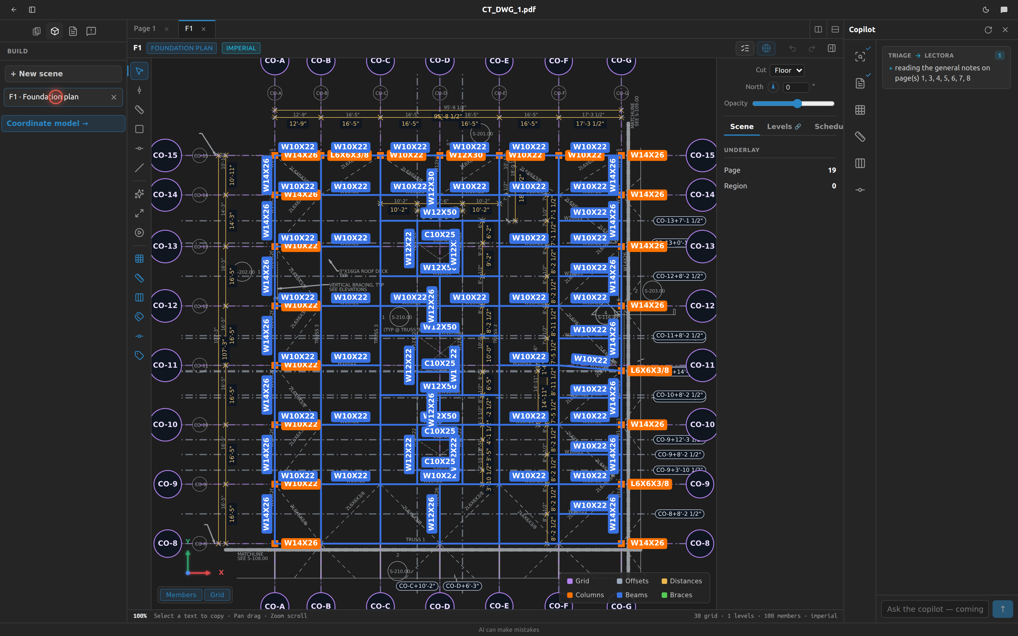
A plan is a horizontal cut. It sights down a column and reports the section it sees at that one point — nothing about where the column starts or stops. An elevation draws the whole member, from a stated bottom to a stated top. That is how a column gets a height.
Why this is not a plan turned on its side
On a plan, a member end is named by two grid lines: A crossed with 2. On an elevation there is only one family of grid lines on the sheet — the verticals — so an end is named by one grid line and a height: A at 42'-0". Everything else on this page follows from that. The verticals come from the Grid tool. The heights have to come from somewhere, and there are exactly three things that can state one: a project level, an offset elevation, or a slant line.
It also means a plan and an elevation can check each other. Where a plan sights a column inside a span your elevation states, the two must name the same section. When they disagree, validation raises it.
Trace an elevation, end to end
- Draw the verticals. Pick Grid line (G) and click each drawn column line, then click its bubble text to name it —
CO-A,CO-B, and so on. Click a horizontal by mistake and Fablnx saysThat is a level, not a grid line — use the Level tool (L). - Draw the horizontals. Pick Level line (L) and click each horizontal rule the frame uses. Each click makes that height buildable — see the three kinds of datum below.
- Calibrate. Pick Dimension (K), click two grid lines, then type the bay distance or click the dimension string on the sheet. On an elevation this also reads the sheet's vertical scale, which offset elevations need.
- Set Runs along. Switch to Select (V) with nothing selected and name the grid lines this frame is taken along. See Say which grids this elevation runs along. Without at least one, the scene cannot be committed.
- Fill from the model. Run Fill from the model to bring in what the committed plans already know along those grids. What is left on screen is the difference between the plans and this sheet.
- Place the rest by hand. Pick Member (M) and click two intersections per member. See Place members.
TIP
Steps 1–3 and 5 all have an AI equivalent in the AI detect group on the rail — Detect grid lines & levels, Calibrate — read dimension ticks, bays and floor heights, and Fill from the model — bring in what Tekla holds along these grids. Detection never runs on its own; you trigger each step. See Detection.
The elevation tool rail
Six tools, in rail order. The tooltips are what the app shows.
| Tool | Tooltip | Key | Unlocked once |
|---|---|---|---|
| Select | Select | V | always available |
| Grid line | Grid line — click a vertical the sheet crosses | G | always available |
| Level line | Level line — click a horizontal, or its "TOS EL" text | L | always available |
| Slant line | Slant line — two intersections a slope runs between | S | always available |
| Dimension | Dimension — two grid lines + a distance | K | a grid line exists (— Draw grid lines first) |
| Member | Member — two intersections; vertical is a column, level is a beam | M | a level is pinned (— Pin a level first (Level tool, L)) |
There is no Column, Beam or Brace tool on an elevation. The single Member tool places all three and works out which from what you drew. Below the tools sit Fit view (F), Review this sheet, and the three AI detect steps.
Things that do not work as labelled
- Left-clicking a level line does not open its properties panel. Nothing is selected and nothing highlights.
- Right-click → Delete on a level line or a slant line reads
Delete grid undefinedand does nothing. Delete them from the inspector list instead (the bin on the row). - The elevation grid table still prints a
Levelcolumn header even though a vertical has no single elevation, so no cell sits under it. The delete button lands there instead.
The three kinds of datum
Steel on an elevation can only be placed where a vertical crosses a height this sheet states. Three things state a height, and they look different on the canvas so you never read one as another.
| Project level | Offset elevation | Slant line | |
|---|---|---|---|
| Colour | teal | rose | orange #f0a35e |
| Drawn as | solid rule | dashed rule | line past both ends |
| Height comes from | the project's level schedule | itself | interpolated between its two ends |
| Label | the level's name | L2+3'-6" | S1, S2, … |
| Can be re-pointed | yes | no | rename only |
Pin a project level (teal)
- Pick Level line (L).
- Click a horizontal drawing line. Click something that is not horizontal and Fablnx flashes
Click a horizontal drawing line — that is where a level sits. - The
Which level is this line?chooser opens at the line. Pick a level — highest first, each with its elevation. Levels already drawn on this sheet are disabled with{name} is already on this sheet. - No level fits?
New level…takes aName, e.g. LEVEL 2and anElevation, e.g. 42'-0", thenAdd & pin. The level joins the project's schedule immediately and shows up in Structure.
Shortcut: if your click lands on a text that reads as an elevation — TOS EL 42'-0", or just 42'-0" — and it matches a project level exactly, the chooser is skipped and the level is pinned in one click.
With no levels at all, the chooser says No project levels yet — name this one and it becomes the building's.
The level owns its height, so renaming it or moving it in the Structure panel follows everywhere — this sheet, every other sheet, and the model. Select the drawn rule and its Level dropdown re-points it at a different level; the steel standing on it moves to the new elevation with it. Levels this sheet already draws are left out of that list, and the app refuses That level is already on this sheet or That level states no elevation.
Place an offset elevation (rose, dashed)
For a height the drawing dimensions and no level names — a base plate at BO BASE PLATE EL 13'-5 1/2", a mezzanine, the underside of a rafter.
- Pick Level line (L) and click the horizontal.
- In the inspector, press the wide button
Place an offset elevation hereinstead of choosing a level.
It is named from the nearest named rule at or below it, so it reads L2+3'-6" — always a positive offset. That is the same scheme that names an offset grid line CO-10+14'-11" on a plan.
Two things must be true first, or you get told:
Pin a level first — an offset is measured from one.Calibrate the sheet first — an offset needs its scale.
And {anchor} is already drawn at that height. if the rule is already there.
Why an offset is not a floor, and never becomes one
The same callout can appear three times on one sheet at three different heights. If every dimensioned rule were promoted to a project level, the schedule would fill with floors the building does not have, and every other sheet would inherit them. An offset states its own height and nothing else's, which is why it cannot be re-pointed at a level and why it is drawn dashed: it is this sheet's own measurement, not something the drawings named.
Draw a slant line (orange)
A rafter. A beam framing into one sits at whatever height the rafter is at that grid line, not at a level.
- Click the Slant line tool in the rail (the
Skey does nothing). - Click two intersections — the rafter's low end and its high end. Both must be on a pinned level, never on another slope. A click that hits no level work point does nothing at all.
- The slope is drawn orange, extended past each end, with its label
S1boxed at the higher end.
Refusals: A slope needs two different grid lines — that is a column. and A slope starts from a pinned level — that point states no height.
Every vertical the slope crosses inside its own span becomes buildable. Switch back to Member and frame to it exactly as you would to a level. Hover any crossing and the height there is read out in feet and inches. Outside its span the slope offers nothing — that is where it stops being drawn.
Station along the slope
A sheet dimensions a rafter along its length — 6 SPA @ 8'-0". Those are measured along the slope, not across the sheet.
- Calibrate the sheet first. Uncalibrated, the field is disabled and reads
Calibrate (K) first — a slope distance is a real length. - Click the slope's row in the
Slopes (n)list to select it. - Type the distance into
Station along {label}→Distance(placeholder8'-0") and press Enter.
Fablnx converts that hypotenuse to a horizontal run and places a grid line there, named from its position: Station placed 8'-0" along S1. The hint reads Measured along the slope, as the sheet dimensions it. Places a grid line at the run it works out to.
A slope takes over from the levels it spans
Between its two ends, the slope supersedes the two levels you started and ended it on, and only between its two grid lines. Those crossings stop being places you can put steel — the roof line there is the rafter, not a flat rule. Every other level is untouched; floors and column bases under a rafter are still there to build on.
Starting a new slope is the exception. A superseded crossing is still offered as a slope work point, so a gable's second rafter can start where the first one ends.
Deleting a slope
The inspector row's bin removes it — unless beams record it: That slope still carries {N} member(s) — move or delete them first. Only beams that actually record on_slant count; steel that merely sits at a height the slope passes through keeps that height and does not block the delete. The next label is always one above the highest still on the sheet, so deleting S1 while S2 is there leaves the next one S3. Delete them all and numbering restarts at S1.
Steel records its height, not the datum
This is the one behaviour that surprises everyone
None of the three datums cascade onto steel. A member end records a grid line and a height in feet — never the name of the level, offset or slope you read it off.
Delete a level line, an offset or a slope and no member is deleted. Those members simply stop being drawn, because nothing on the sheet states their height any more. They are still in the model, and the member table in the inspector still lists them, each row showing its own heights. State that height again — pin the level back, place an offset there — and they reappear where they always were.
The one thing that does move steel is re-pointing a drawn level at a different project level from the properties panel: every end at the old height is restated at the new one, deliberately.
Why it works this way
A rule on a drawing is a reading aid; the elevation of a piece of steel is a fact. If members hung off the rule, tidying a sheet — removing a horizontal you traced by mistake — would silently destroy work, and redrawing a rafter would drag framing to new heights nobody approved. Recording the height instead means removing a rule you no longer want never costs you anything, and a redrawn rafter leaves the old framing where you put it.
The flip side: redraw a rafter and check the framing on it. Beams that followed the old line stay at the old heights and go quiet until something states them again.
Place members
The Member tool (M) is locked until a level is pinned. Until then the hint reads Pin a level first — Level tool (L), click a horizontal line.
- Click two intersections, or drag from base to top.
- Fablnx infers what you drew:
| What you drew | What you get |
|---|---|
| Both ends on the same grid line | a column |
| Both ends at the same height | a beam |
| Anything else (a diagonal) | the chooser Diagonal — which is it? → Brace or Sloped beam |
The diagonal chooser opens at the click point; Esc dismisses it. A brace and a sloped beam are the same line on a sheet, so the drawing cannot decide it for you.
An end can sit between two levels
Steel does not only stand floor to floor — a post lands on a beam part-way up a storey, or stops short below the floor above. Click a grid line anywhere between two levels and Fablnx places an offset elevation at that height first, then puts the end on it. The height appears in the Elevations list of the Level tool, named off the nearest rule below it (L2+4'-6"), where you can read it, correct it or take it off again.
That is why it mints a line rather than just remembering a number: an end is a grid line and a height, and a height is only somewhere on the page once something on the page states it. Without the rule the member could be recorded and never drawn.
If the sheet is not calibrated, or no level is pinned yet, the click says so instead — an offset is measured from a named rule and needs the vertical scale.
Refusals:
A column is vertical — {A} and {B} are two different lines. Use Brace for a diagonal.A column needs two different heights.
Drag to place a run. A drag places one member from the first node to the last; the levels it passes through are passed through, not stops. So a shaft that does not change section stays one piece in the bill of materials — drag from base plate to top of steel and type the section once.
In the inspector the list reads Members (n) and holds all three kinds; the table's first column is On line, and each row states its own heights (CO-A 0'-0"→42'-0") rather than a level's name. There is no Orientation control in the elevation member tool panel, and no Rotation control in a selected member's properties either — a lateral view cannot show which way a column's strong axis is turned. Set it on the plan that draws the same station.
Say which grids this elevation runs along
An elevation is not created at a level. It is a plane perpendicular to the grid lines it crosses, and those lines do not exist when you create the scene — so the question is asked here instead.
- Pick Select (V) and select nothing.
- In the inspector, open the
Runs alongsection. - Open a direction fold and click the grid labels this drawing stands for.
Locked until this sheet has a grid line, with the message Draw or detect a grid line on this sheet first.
- Lines are folded by direction family, one fold per direction, each summary showing the angle those lines run at, how many lines it holds, and how many you have picked — so a shut fold still tells you what is chosen.
- Only named grid lines are offered. Offsets and station labels like
CO-10+14'-11"never are; no drawing is taken along one. - The family this sheet draws itself is excluded — a frame crosses its own verticals, it cannot also lie along one.
- Shift-click takes the whole run between the last chip you clicked and this one, so a sheet titled ELEVATION ALONG GRIDS B,C,D,F,G,H & I is two clicks, not seven.
- Once you pick one, only grids parallel to it stay on offer. An elevation is a single plane.
The footer tells you where you stand: {n} frames from this drawing., or One frame. Shift-click for a run of them., or Name at least one grid line, or this drawing has nowhere to go.
Nothing offered at all reads: Nothing this sheet could run along. Trace a plan that places a line crossing the grid you drew, and the planes perpendicular to it appear here.
TIP
An elevation that names no grid can be traced, saved and worked on as much as you like — it just cannot be committed, because it has nowhere in the building to go. See Validation & the world.
There is deliberately no facing field. Members anchor by grid label, not by which way the sheet looks.
The layer chips
Bottom-right of the canvas. An elevation has eleven — the nine a plan has, plus two of its own. Click one to hide or show it; off is muted and struck through.
| Row | Chips |
|---|---|
| Grid | Grid (violet) · Offsets (slate) · Distances (amber) |
| Members | Columns (orange) · Beams (blue) · Braces (green) |
| Profiles | Column profiles · Beam profiles · Brace profiles |
| Elevation only | Levels (teal) · Offset elevations (rose) |
Above them is an All layers checkbox — clear it and every chip goes at once, tick it and they all come back — so an elevation is cleared without switching off Levels and Offset elevations by hand every time.
The vertical family and the horizontal family get different hues on purpose, so a datum is never read as the wrong kind — and within each family the offset is the dimmer, dashed one. A member's line and its profile tag are separate switches, so you can check framing without a tag on every piece, or read the sections with the linework quiet. Slant lines have no chip; they are always drawn.
Where to go next
- Validation & the world — validate the sheet, then commit it.
- Structure — the level schedule every pinned level comes from.
- Detection — the three AI steps an elevation offers.
- Glossary — station, offset elevation, run along.
- Keyboard shortcuts — every key an elevation uses.