Appearance
The coordinated 3D model
Every scene you validate and commit lands in one place: the coordinated model — the 3D view of the whole building, with the tools a detailer expects. Orbit it, section it, measure it, colour it by grade or level, and take a material takeoff off it.
You'd be on this tab to check that the sheets agree with each other: that a column actually lands on the beam below it, that a level is framed the way the elevation says, that nothing is missing before you issue.
The 3D model is read-only
You cannot move, delete or edit steel here. Fix a member in the scene it came from, then revalidate and commit — the model re-solves itself. The properties dock says the same thing at its foot: "Edit members in their source scene, then revalidate & commit."
Open the model
- Open the Structure panel in the sidebar.
- Click Model (sub-hint "Coordinated 3D model").
It opens as an editor tab, so you can split it right or down and keep a scene beside it like any other tab.
Nothing here needs refreshing. The model re-solves itself every time a scene joins or leaves the world — a commit or a withdraw, in this window or another one. There is no Refresh button anywhere in this tab, on purpose.
What you see before there is a building
With no committed scenes, the whole viewer is replaced by a single line:
"No world model yet — validate a scene and commit it to see it here."
No ribbon, no status bar, nothing else. Trace one scene and the full tab appears. While the 3D engine loads you'll briefly see "Loading 3D…".
One more consequence of live-ness: your selection, your manual hides and your selection filter all reset whenever a fresh model arrives. If a colleague commits a scene while you have something isolated, the isolate clears.
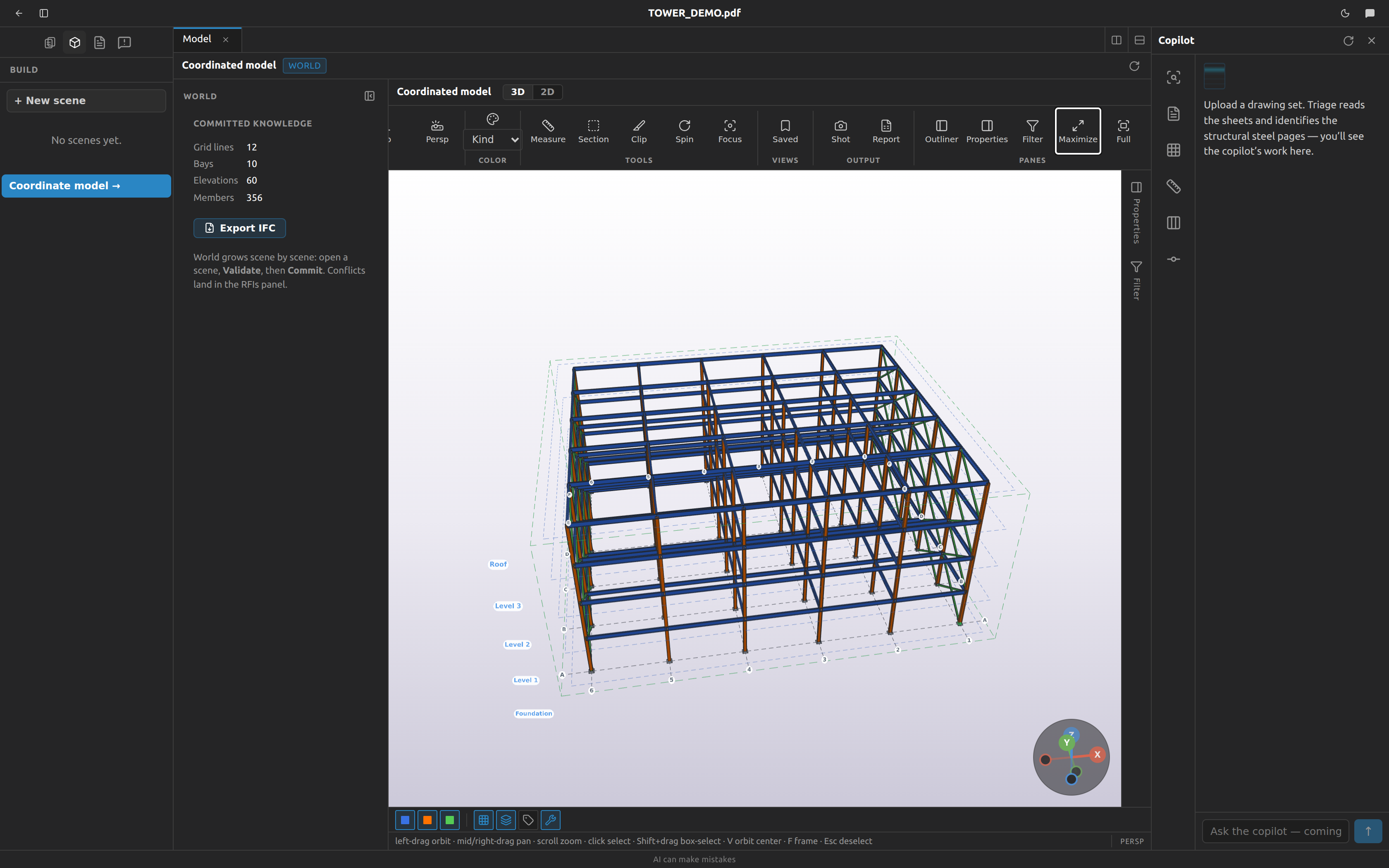
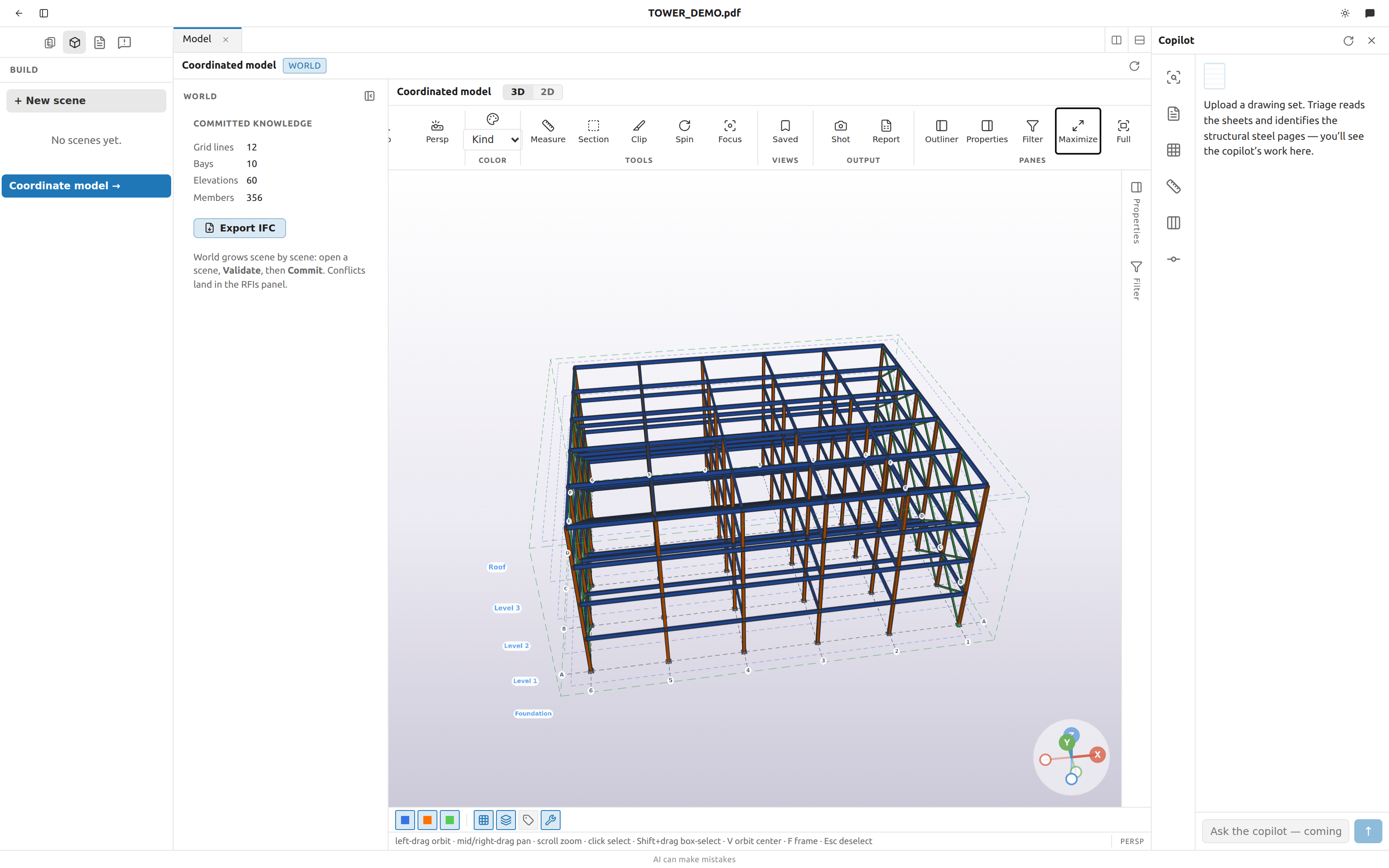
The tab is the model and nothing else:
| Where | What |
|---|---|
| Across the top | The ribbon — every command, icon over label |
| Left dock | The Outliner — the model tree |
| Centre | The 3D viewport, with the axis gizmo in the corner |
| Over the viewport | The breadcrumb — where you are, back and forward, and the parts you last selected |
| Right dock | Properties, and the selection Filter below it |
| Under the viewport | The switch rail — category toggles — with the bay chip and the storey rail beside it |
| Bottom | The status bar |
The ribbon
Groups are separated by hairlines, each with a small caption underneath. No ribbon button is ever greyed out — the only disabled control in the ribbon is Save inside the saved-views popover, which waits for a name.
Group View
| Button | Tooltip | What you get |
|---|---|---|
| Solid | Solid | Opaque shaded members with edge lines. The default. |
| Wire | Wire | Pure wireframe — the faces go fully transparent, the edges stay. |
| X-ray | X-ray | See-through steel, so you can read what's behind it. |
| Iso | Isometric (Home) | Snaps to the standard isometric view. |
| Ortho / Persp | Perspective / orthographic (Num5) | Switches the camera projection. |
The projection button names the state, not the action
The button reads Ortho while the camera is orthographic, and Persp while it is perspective. The status bar's right-hand readout shows the same word. Read it as a label, not as a promise of what the click will do.
Group Color
A Color members by dropdown with five options:
| Mode | Colours by | Notes |
|---|---|---|
| Kind | Beam / column / brace | The default. Beams blue, columns orange, braces green. |
| Grade | The member's grade, e.g. A992 | Legend caption reads By grade |
| Level | The member's level, labelled with the level name | Legend caption reads By level |
| Profile | The profile family letter, not the full designation | Legend caption reads By profile |
| Sheets behind it | How many drawings describe each member | Four fixed bands — see below |
Colour by how many drawings describe it
Sheets behind it is the coverage read, and it has four bands rather than a colour per value:
| Band | Colour | What it means |
|---|---|---|
| No drawing | Red | The finding. Steel detailed from nothing — modelled by hand, or the drawing that stated it has gone |
| One sheet | Amber | One drawing states it and nothing corroborates it |
| Two sheets | Blue | Two drawings state it |
| Three or more | Green | Three drawings agree, which is worth knowing too |
Colour rather than a table, because coverage is a place fact: a bay with no drawings behind it shows up as a patch, and no list makes a patch visible. Only the bands that actually occur appear in the legend, each with its count.
There is no legend in the default view
The colour legend is hidden entirely in Kind mode. It only appears — bottom-left over the viewport — once you pick Grade, Level or Profile.
Two things about Profile colouring surprise people:
- It groups by family letter, so
W8X31,W14X90andW21X44are all one colour, under W.2L4X4files under L,PL1/2under PL. - The palette holds 14 colours and then cycles. With more than 14 grades, levels or families, two buckets share a colour — read the legend, not the colour.
Members with no value for the chosen attribute get their own bucket labelled —. Legend counts are for the whole model, not just what's visible.
What colouring does to selection
Selected steel turns yellow, replacing its colour entirely — the Tekla convention. The member under your cursor darkens slightly. Everything else keeps its colour-by colour. Colour changes apply in place; nothing is rebuilt, so switching modes is instant.
Group Tools
| Button | Tooltip | What it does |
|---|---|---|
| Measure | Measure | The measure tool — see Measure something. |
| Section | Section box | A six-handled box you drag to cut the model open. |
| Clip | Z clip plane | A horizontal plane that hides everything above it. |
| Spin | Auto-rotate | Slowly orbits the model on its own. |
| Focus | Frame selection (F) | Zooms to fit the selection, or the whole model if nothing is selected. |
Which tools cancel which
The three cutting/measuring tools are mutually exclusive, but not symmetrically:
- Turning Clip on clears the Section box.
- Turning the Section box on clears both Measure and Clip.
- Turning Measure on clears the Section box — but Clip stays on, so you can measure inside a clipped model.
Group Views
One button, Saved (Saved views) — see Save a view.
Group Output
| Button | Tooltip | What it does |
|---|---|---|
| Shot | Snapshot PNG | Renders one clean frame and downloads it as <project-id>-view.png — e.g. 7-view.png. |
| Report | Material takeoff (ABM) | Opens the takeoff — see Material takeoff & export. |
Group Panes
| Button | Tooltip | What it does |
|---|---|---|
| Outliner | Outliner | Shows/hides the left model tree. |
| Properties | Properties | Shows/hides the properties dock. |
| Filter | Filter | Shows/hides the selection filter. |
| Maximize | Maximize viewport | Hides the Outliner, Properties and Filter in one click. |
| Full | Fullscreen | Browser fullscreen on the viewer. Esc comes back out. |
Maximize is one-way
Maximize is not a toggle. It hides all three panes and there is no restore button — clicking it again does nothing. Bring each pane back individually with Outliner, Properties and Filter, or from the tab strip on the far right edge.
Show and hide whole categories
The switch rail sits under the viewport. The labels are tooltips only — there is no visible text.
| Toggle | Shows | Default |
|---|---|---|
| Beams (blue dot) | Every beam | On |
| Columns (orange dot) | Every column | On |
| Braces (green dot) | Every brace | On |
| Grid | The dashed grid lines and their bubble labels | On |
| Levels | The dashed level rectangles and the level name pills | On |
| Marks | The part-mark bubbles at each member's midpoint | Off |
| Connections (base plates, bolts) | Derived base plates, shear tabs, gussets and bolts | On |
Turning Grid off also stops measuring to grid intersections
The Grid switch does double duty: it hides the grid lines and removes every grid-intersection snap point from the measure tool. If your snap ring stopped appearing at bay corners, check that switch.
Turning a kind off also removes those members from box-select and from the Same profile / Same kind / Same level buttons in the properties dock. Those buttons only ever select steel that is currently selectable.
What the connection steel actually is
Base plates, shear tabs, gussets and bolts are derived from the geometry, not designed. They are a fabrication-plausible approximation drawn so the model reads like steel — a base plate on every ground-floor column, a tab where a beam end meets a column, a gusset at each brace end. They are deliberately not selectable: you can't click, hover, measure or box-select them.
They also affect one number. With Connections on, the no-selection Weight in the properties dock includes the plate steel; turn it off and that weight drops. The material takeoff never includes them either way — see the two weight totals.
Focus on a floor, or on one sheet
Under the viewport, the storey rail says what the view is about.
A detailer does not look at a whole building — they look at a floor. Click a level on the rail and you get that floor solid, everything under it faint enough to say where it sits, and everything over it out of the way. The button's tooltip reads <level> and below. Levels run top to bottom, the way an elevation is drawn.
After the levels, the rail lists your sheets. Click one and you get this sheet in 3D: the steel that drawing drew, solid, with the rest of the building faint around it (Only what <sheet> drew). It is the fastest way to answer did I draw all of this floor — a Tekla member says nothing about which sheet drew it, so this is a question only Fablnx can answer.
A chip at the end of the rail says what you are looking at — Level 2 and below, or S2.1 only — and clicking its × puts the whole building back. Clicking the lit button again does the same.
Focus is a third state, not a filter
Faint steel is context, not subject. It has no edges, and it is deliberately absent from the pick, hover, measure and box-select sets: something you can accidentally click is not context, it is a trap.
A member with no level is placed by its own highest point. One whose elevation cannot be established at all is drawn as context rather than as subject, because claiming it is on this floor would be an answer Fablnx does not have.
A sheet that drew nothing in this model is not entered at all — it would ghost the whole building and show you no subject.
Lay the drawing under the model
Beside each sheet on the rail is a small picture button (Lay this drawing in the model). It puts that sheet's drawing where the building is — flat, at the level the sheet cuts, under the steel.
Inside Tekla Structures it inserts a real reference model. Vector linework, placed exactly, that you can work over and snap to like any reference drawing you would insert by hand — except you do not have to place it, because Fablnx already solved the grid. Turn the button off and the reference model is taken away again.
In an ordinary browser you get the same drawing in the 3D view, laid at the same elevation. Use the slider under the sheets to fade the drawings up and down.
The tooltip tells you how well the drawing is placed:
- matches to 2 1/4" over 6 crossings — the drawing and its own dimensions agree.
- placed on 1 crossing — not checked against a second — it is in the right place as far as anything can tell, but only one grid crossing was available to check it against.
- the drawing disagrees with its dimensions by 9" — the linework and the dimensioned bays do not tell the same story. Worth an RFI.
The drawing is not a measurement
Distances in Fablnx come from the dimensions, never from the linework. A drawing laid in the 3D view is there to be looked at: you cannot select it, snap to it or measure against it, and it does not affect zoom-to-fit.
Inside Tekla you can snap to it, and that is deliberate — there you are the one deciding, and a correction you make against the drawing is exactly what Fablnx wants to hear back.
A sheet that cannot be laid down says why instead of doing nothing: it has no scale yet, it shares no grid line with the building, it is an elevation rather than a plan, or four drawings are already down and the fifth is waiting for one to be turned off.
Make a Tekla plan view at a level
With a level focused inside Tekla Structures, a Tekla view button appears on the rail (Make a Tekla plan view at this level). One click creates a real Tekla plan view at that elevation, named after the level — Tekla's own view, that you can dimension in, snap in and draw from. It is a chore every job repeats dozens of times.
The button is not there in an ordinary browser: there is no Tekla to make a view in.
Cut to a bay
Beside the storey rail, the bay chip clips the view to one bay of the grid — named the way the job already names it.
- Pick one corner from the first dropdown: a grid intersection, like
A-1. - Pick the opposite corner from the second:
C-4. - The view clips to that bay, and the chip says what it cut and how many members are in it.
Both dropdowns offer only intersections your grid actually carries. A pair that shares a grid line is refused in words on the chip rather than leaving a box that looks broken. The × clears it.
The bay is bounded in plan and unbounded vertically, on purpose: which storey you want is the storey rail's question, not this one. And it takes anything the bay touches, not only what is wholly inside — a bay's girder carries on into the next one, and a clipped view missing an edge reads as steel missing from the model.
Navigate the model
| Input | Action |
|---|---|
| Left-drag | Orbit |
| Middle-drag or right-drag | Pan |
| Scroll | Zoom, towards the cursor |
| Click a member | Select it |
| Click empty space | Deselect everything |
| Shift + click | Add to the selection |
| ⌘/Ctrl + click | Toggle in the selection |
| Shift + drag | Box-select |
| Double-click a member | Select and isolate it |
| Double-click empty space | Show everything again |
Keyboard
| Key | Action | Works when |
|---|---|---|
| Num 1 | Front view | Anywhere in the workspace |
| Num 3 | Side view | Anywhere in the workspace |
| Num 7 | Top view | Anywhere in the workspace |
| Num 5 | Orthographic / perspective | Anywhere in the workspace |
| Num . | Frame the selection | Anywhere in the workspace |
| Home | Isometric view | Anywhere in the workspace |
| F | Frame the selection | Pointer over the 3D canvas |
| H | Hide the selection | Pointer over the canvas, with a selection |
| I | Isolate the selection | Pointer over the canvas, with a selection |
| V | Set the orbit centre to the point under the cursor | Pointer over a member |
| Esc | Cancel a box-select, close the saved-views popover, exit the section box, exit measure, then deselect | Mixed |
Two groups of keys, two different rules
The six view keys — Num 1 / 3 / 7 / 5 / . and Home — are claimed app-wide the whole time the Model tab is open, even when you're clicked into another pane. F, H and I need the pointer over the 3D canvas. Typing into any text box is never intercepted.
View changes are animated over about a quarter of a second, not instant. Grabbing the mouse cancels an animation in flight.
The axis gizmo
The gizmo in the viewport corner (tooltip Snap to axis view) spins with the camera. Click the X, Y or Z ball to snap to that axis view. You don't have to hit the ball — clicking anywhere inside its disc snaps to the nearest axis.
Box-select: window and crossing
| Drag direction | Band | Catches |
|---|---|---|
| Left → right | Solid blue | Only members fully inside the rectangle |
| Right → left | Dashed green | Any member the rectangle touches |
Hold Shift to add to the selection or ⌘/Ctrl to toggle — the modifier is read when you release. Esc mid-drag cancels. Clipped-away members are never caught.
Why a box-select is sometimes approximate
Membership is tested against each member's bounding box, not its true outline. A tight diagonal brace can slip out of a window selection, and a crossing selection can pick up a neighbour whose box overlaps. For anything exact, use the model tree or the filter.
Cut the model open
Section box — turn it on and the box fits itself around the model. Drag any of the six blue face handles along its axis to move that face. The camera locks while you drag, and a face can never cross its opposite. While the box is on, clicks land on handles rather than steel, and picking ignores anything outside the box.
Clip — a vertical slider appears on the right edge of the canvas (Z clip plane) with a live elevation readout. It runs between the lowest and highest level and opens at the top with nothing clipped. Drag it down and everything above the plane disappears, including connection steel and mark bubbles. Picking and box-select honour it.
If both are somehow on, the section box wins.
Know where you are
A line of chrome over the viewport always says where the camera is looking, in the words a detailer would use out loud: Level 2 · near C-4. It updates as you move. Off the grid entirely — more than about a bay from any intersection — it reads off the grid.
The level is the storey you are on: the highest level at or below the height you are looking at, which is what a drawing means. Under the lowest level it says nothing rather than naming a floor you are beneath.
Back and forward
The ‹ and › buttons beside it walk the places you have been, with the two keys everybody already knows the meaning of.
Back goes through places, not through mouse moves. A place is recorded when you navigate — a view preset, framing a selection, opening a saved view, jumping from the command palette or from the recent list. Orbiting is not navigating: recording the camera every time it settles would leave you with forty entries and none of them anywhere you meant to be.
Going somewhere new from part-way back drops the forward trail, exactly as a browser does.
Recent parts
After the breadcrumb, the last few parts you selected are listed by profile, newest first (The last parts you selected). Click one to select and frame it again — a half-finished train of thought is recoverable.
Only single selections are remembered. A box-select of forty is not a thing you looked at, and putting it in the list would push out the four that were. The list resets when the model itself changes.
Type at the model
Press ⌘/Ctrl + K over the 3D model and a command palette opens. Detailers say grid references out loud all day and then click through three panels to get there; this is the shorter way.
Start typing — the placeholder says what it takes: Grid reference, mark, section, level, sheet… — then ↑ / ↓ to move, Enter to run the highlighted one, Esc to close. Clicking outside closes it too.
| Group | Type | What it does |
|---|---|---|
| Grid | B-3 | Goes to that grid intersection |
| Mark | B14 | Selects every member carrying that mark — which is what a mark is — and frames them |
| Section | W12X26 | Selects every member of that profile |
| Storey | A level name | Focuses that floor: this floor solid, below it faint |
| Sheet | A sheet name | Focuses that drawing: only what it drew |
| View | A saved view's name | Jumps to it. The hint is the view's own note |
| Do | — | Show everything, Isolate the selection, Frame the selection, Check the model |
The list is ranked, not filtered. An exact name beats a prefix, which beats a word start, which beats a substring — so W12 finds W12X26 above HSS12X12X1/2, and the first row is always what Enter will run. A palette where Enter is a gamble is one nobody types blind into, which is the only way anybody types into a palette.
Nothing matching reads Nothing by that name in this model.
Check the model, member by member
Checker mode is the red-pen pass: an ordered walk through every member, with a tick or a flag at each stop. Open it from the command palette — Check the model — and a transport appears over the viewport.
Every stop selects the member here and selects it in Tekla, so you are walking the actual steel rather than a picture of it. It does not move either camera unless you ask it to — see Follow below.
| Control | What it does |
|---|---|
| ‹ / › | Previous, next |
| ▶ / ❚❚ | Play or pause the walk — it advances on its own about every 1.4 seconds |
| ✓ | Correct — records a tick and moves on |
| ⚑ | Wants a look — records a flag and moves on |
| The bar | 12/318 decided, with N flagged beside it once anything is flagged |
| Follow | Whether each stop frames the member — here and in Tekla — or only selects it. Off to start with |
| Walking order | By level or By mark |
| ✕ | Leave the check |
Follow is one switch, shared by every tour
The same Follow pill appears on the scene review's HUD and on the connection schedule's tour. It is one preference: turn it off in one and it is off in all three, because a view that jumps while you are mid-edit is unwelcome wherever it happens. It is remembered in this browser.
Deciding advances. A checker who ticks and then presses next is doing two gestures for one decision, and after four hundred members that is eight hundred.
The two orders
The order is the whole feature — walking a model in whatever sequence it comes back in is not checking, it is scrolling.
- By level — lowest floor first, columns before the steel they carry, then along the plan. It is how a plan is read and how a floor gets signed off.
- By mark — every
B14together, because if one is wrong they all are. It is how a shop reads it. A member with no mark files under unmarked.
A flag is not a delete, and the list is not saved
Flagging says somebody should look at this. It changes nothing in the model and nothing in the scene — the coordinated model is read-only, and a check that quietly deleted steel would be a very different and much worse tool. To remove a wrong member, reject it in the scene review that drew it.
Ticks and flags live in this tab for this session. Leaving the check keeps them, so a pass of four hundred members does not have to be one sitting — but a fresh model arriving clears them, because verdicts about members that may no longer exist would be worse than none.
Point at the same place on the sheet
Split a scene and the Model tab side by side — drag one tab into the other half of the workspace — and the two windows follow each other's pointer.
- Move the pointer over the plan and a blue crosshair moves in the model, at the same place in the building.
- Move it over the steel in the model and a blue ring moves on the plan.
Nothing is calibrated and nothing is typed in. Fablnx works the mapping out from the grid: the sheet's grid lines carry labels, the solved building's carry the same labels, and two crossings that agree on a pair of labels are one place seen twice.
When there is no marker
A sheet only locks when the mapping can actually be worked out, and Fablnx would rather show nothing than a marker in the wrong place. There is no marker when:
- the sheet is an elevation — it is not a map of a floor;
- the sheet's steel sits at several elevations, so there is no one floor to put a marker on;
- fewer than two of the sheet's grid crossings are named in the building — one point fixes no direction and no scale;
- the crossings that do match do not line up, which is what a mislabelled grid line looks like.
Committing the sheet, so its grid reaches the building, is what usually turns the lock on.
Sheets that are not in the model
Over the viewport, a short banner appears when a sheet states steel and none of it is in the model:
2 sheets not in the modelS2.1 (48), S3.0 (31) — stated, and none of it pushed.
It is the list that answers have I detailed everything I was given. A sheet with some of its steel in the model is a job in progress and says nothing; a sheet with none of it has not been pushed. The number in brackets is how many members that sheet states.
The banner hides itself while checker mode is running.
Select and inspect
Browse the model tree
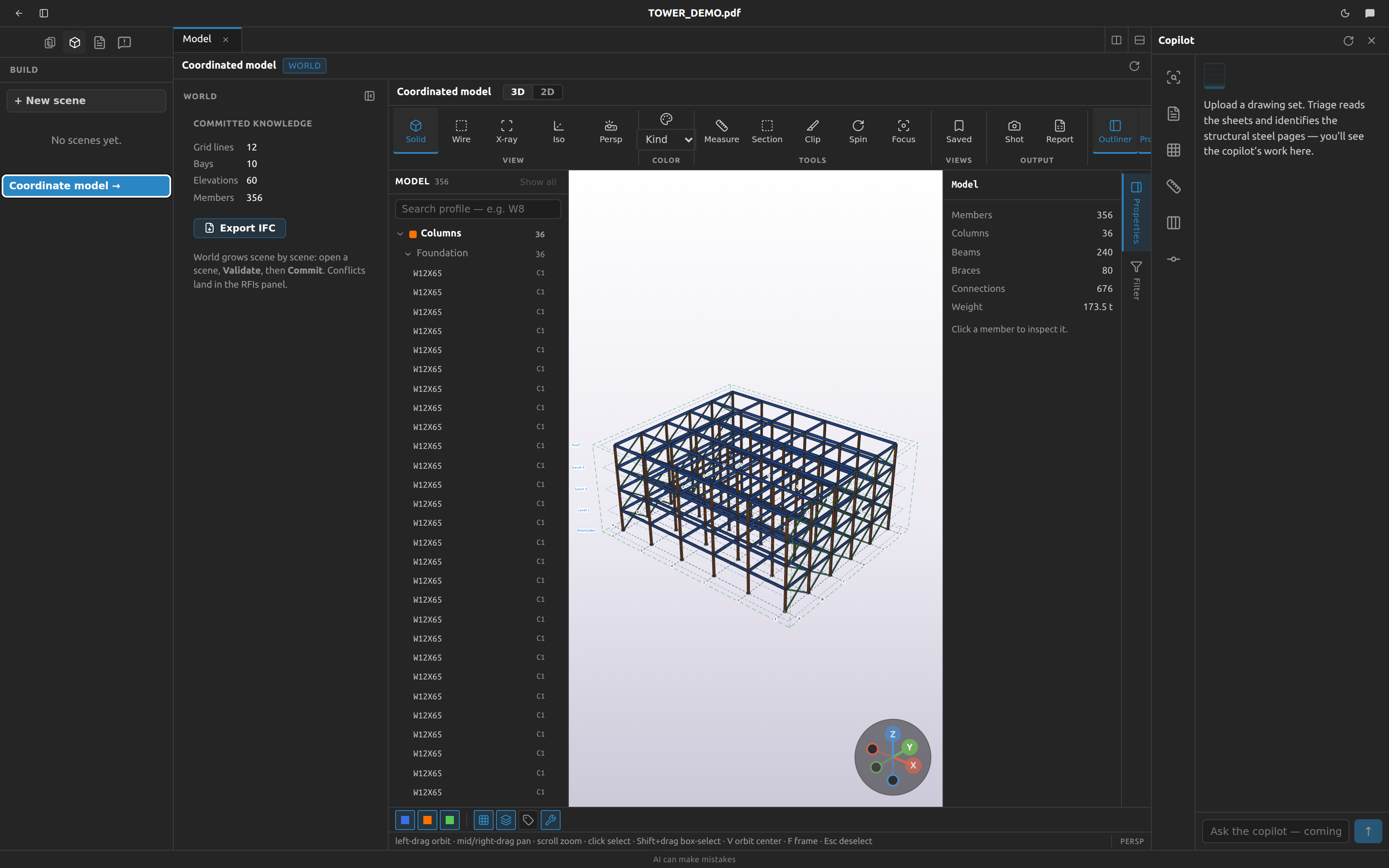
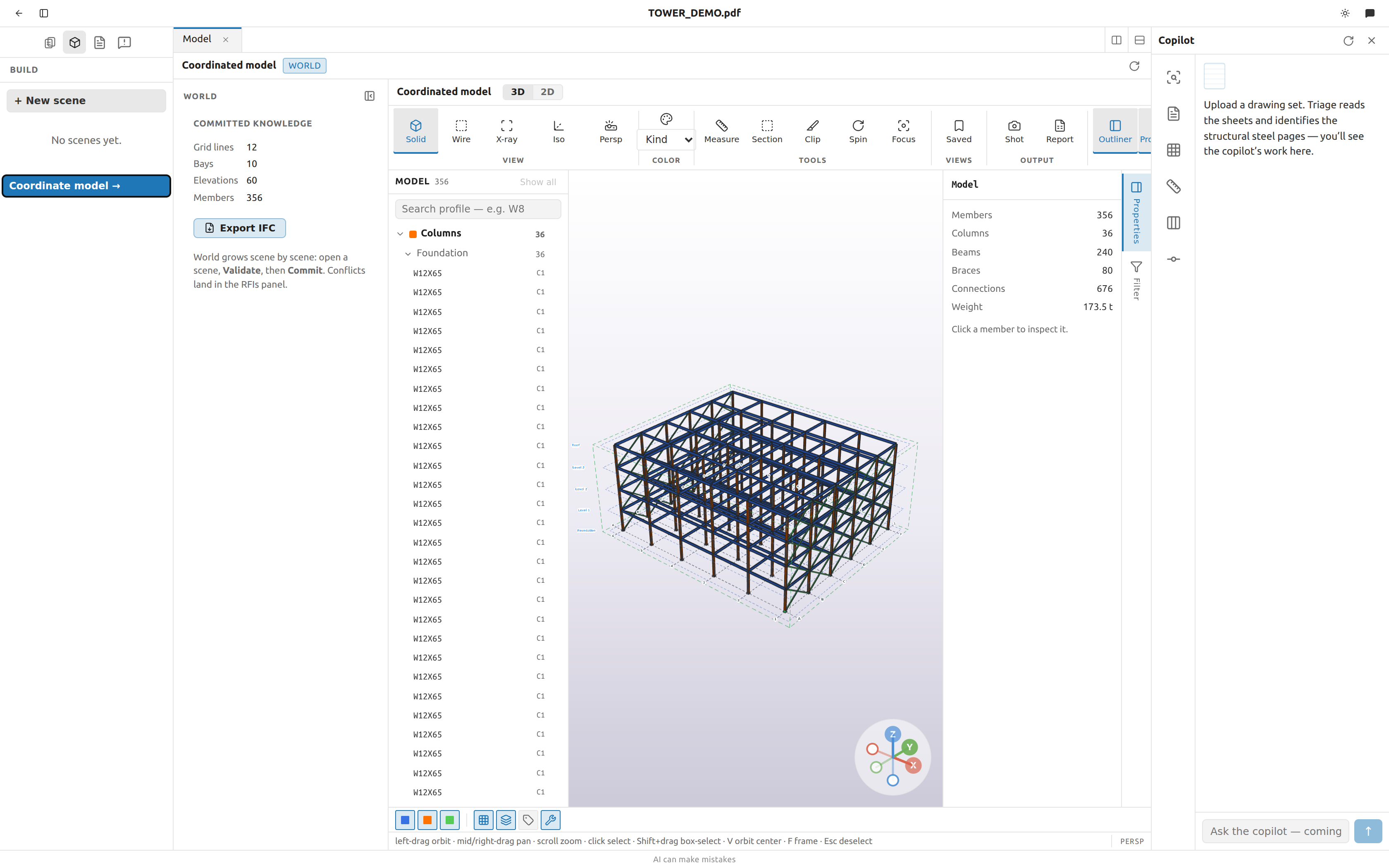
The Outliner is titled Model, with a count badge showing the total members in the model. It groups in two fixed levels: kind → level → member.
- Kinds run Columns, Beams, Braces and are always in that order.
- Level groups sort alphabetically by level name, not by elevation.
- A member with no level sits under —.
- Each leaf shows the profile designation, or — no profile —, plus its mark chip.
| To do this | Do this |
|---|---|
| Find a section | Type in the search box (Search profile — e.g. W8) |
| Select a member | Click its leaf — the camera flies to it and frames it |
| Collapse a group | Click the kind or level row |
| Hide a member or a whole group | Click its eye (Hide) |
| Bring it back | Click the crossed eye (Show) |
| Undo every manual hide | Click Show all |
Search only matches profiles
The box searches the profile designation and nothing else — not marks, not level names, not kinds, not grades. Typing a mark or a level name gives you No members match "…".
"Show all" can look available and do nothing
Show all clears manual hides only. It does not undo the selection Filter. It also decides whether to grey itself out by looking at everything currently hidden, filter included — so when only the Filter is hiding steel, the button is clickable but changes nothing. Clear the Filter with its own Reset.
Read a member's properties
Select one member and the Properties dock shows its profile designation as the title, with a coloured kind dot:
| Row | What it is |
|---|---|
| Mark | The auto part mark, e.g. B7 — see how marks are numbered |
| Type | Beam, Column or Brace |
| Grade | e.g. A992 — only when the member has one |
| Section | Depth × width in inches, e.g. 15.7″ × 5.5″ — only when the section is in the catalog; a catalog entry with no dimensions shows its family letter instead |
| Level | The level name and its elevation |
| Length | The 3D length, in feet and inches to 1/16″ |
| Orient | H, or I (rotated) when the section is turned 90° — columns only; a beam or a brace has no orientation |
| Sheets | How many scenes drew this member — only when more than one did |
Then two rows of buttons:
- Isolate and Hide — visibility only.
- Same profile, Same kind, Same level — replace the selection with everything matching that attribute, limited to steel that is currently selectable (kind switched on, not hidden, not filtered out).
Read totals for several members
Select two or more and the dock's title becomes "N selected":
| Row | What it is |
|---|---|
| Columns / Beams / Braces | Counts, for the kinds present |
| Length | The sum of the lengths |
| Weight | Total tonnage, when it can be worked out |
| CoG X, CoG Y, CoG Z | The centre of gravity, in feet and inches |
Below the rows, the distinct profiles in the selection, listed alphabetically.
See Weigh a selection for what the centre of gravity does when a section isn't in the catalog.
Read the whole-model summary
With nothing selected, the dock is titled Model and shows Members, per-kind counts, Connections (the number of derived plates — bolts aren't counted), and Weight, then the hint "Click a member to inspect it."
These numbers count the whole building
The summary ignores your hides, your filter and the kind switches — it always describes the entire model. The one exception is Connections and its contribution to Weight, which follow the Connections switch. This is also not the same tonnage as the takeoff's; see why two weight totals disagree.
When you have manually hidden anything, a "Show all (N hidden)" button appears here too.
Narrow what you can select
Open Filter to restrict the model to the steel you're working on. Anything that fails the filter disappears from the view, cannot be clicked or box-selected, and is left out of "select similar".
| Facet | What it offers |
|---|---|
| Type | Checkboxes for Beams, Columns, Braces, each with a live count |
| Level | One checkbox per level with its member count, plus — (no level) when some member has none |
| Profile | A text box (e.g. W8) matching any part of the designation |
A member survives when its type is ticked and its level is ticked and it matches the profile text. Reset puts everything back.
Measure something
- Click Measure in the ribbon.
- Pick the mode in the status bar — Dist, Angle or Gap. This is the only place the mode can be chosen.
- Click in the viewport as the prompt asks.
- Read the result in the status bar.
| Mode | You click | You get |
|---|---|---|
| Dist | Two points | The straight-line 3D distance, in feet and inches |
| Angle | Two members | The acute angle between their axes, to 0.1° |
| Gap | Two members | The shortest clearance between the two work lines |
In Dist mode an amber ring shows when a snap is in reach. Snaps are the two ends and the midpoint of every visible member, plus every grid intersection at every level. With no snap in range, the point under your cursor is used as-is.
Switching mode clears the current measurement; a third click in Dist starts a fresh one. Turning Measure off, or pressing Esc over the canvas, clears everything it drew.
A distance is printed with where it was taken — 4' - 6 1/2" at level 2 · near C-4 — because a bare number is one you have to hold in your head while you work out where you were. Nothing is added when there is nothing to add: off the grid, the figure prints on its own rather than with a hedge. Angles carry no place, because an angle is between two members rather than at a point.
Gap measures work lines, not steel faces
Gap reports the clearance between the two members' work-line segments, not between their drawn flanges. Two members whose steel is touching can still report a gap, and vice versa. Use it for setting-out clearance, not for fit-up.
Angles always read acute
An angle is reported as the acute angle between the two axes, so two members pointing in opposite directions along the same line read 0°, not 180°. Clicking the same member twice is ignored.
Save a view
- Click Saved in the ribbon.
- Type a name in the Name box.
- Type a reason in the Why (optional) box.
- Click Save, or press Enter in either box.
To jump to a view, open the popover and click its name. To delete one, click its × (Delete view). With none saved, the popover reads "No saved views". Esc closes it.
The note is what makes it a bookmark rather than a camera preset. "The messy corner at C-4, waiting on the EOR" is the reason to come back, and a list of names with no reasons is one nobody revisits. It shows under the name in the popover and is the view's hint in the command palette.
The model opens where you left it
Separately from saved views, the camera you left the 3D tab on is remembered per project and restored the next time you open it, so opening the model twice in a morning does not start from the default isometric both times.
It is only the camera. What you had selected and what you had focused are answers to questions that may not be true any more, so neither comes back.
Saved views are local to your browser, and store only the camera
Four things to know before you rely on them:
- They live in this browser on this machine, per project. They are not synced, not shared with your team, and not backed up — a colleague opening the same project sees none of them, and private-browsing loses them when the window closes.
- They store the camera only: position, target, up, and whether it's orthographic. They do not store your shading mode, colour-by mode, hidden members, filter or section box. Jumping to a view moves the camera and nothing else.
- Saving a name that already exists overwrites it without asking.
- × deletes immediately, with no confirmation.
Read the status bar
The right-hand end always shows Ortho or Persp for the current projection, and with anything selected, "N selected" — plus the tonnage once you have two or more members with catalog weights.
The left-hand end changes with what you're doing:
- Nothing selected — "left-drag orbit · mid/right-drag pan · scroll zoom · click select · Shift+drag box-select · V orbit center · F frame · Esc deselect"
- Something selected — "H hide · I isolate · M move · Del delete · Ctrl+Z undo · F frame · Esc deselect"
- Measuring — the three mode chips and the prompt or result.
Ignore "M move", "Del delete" and "Ctrl+Z undo"
The selection hint advertises three keys that do nothing in this tab. The 3D model is read-only: there is no move, no delete and no undo here. Change the member in the scene that drew it, then revalidate and commit. The keys that do work from that hint are H, I, F and Esc.
There is no clash detection yet
The status bar has a slot for a "⚠ N in clash" count, and the properties dock has a red ⚠ clash chip. Nothing ever fills them — clash checking is not switched on in this build, so the count never appears and no member is ever coloured red. Don't read a clean status bar as a clash check.
What else is in the picture
Things you'll see that aren't controls:
| You see | What it is |
|---|---|
| A light grey-violet background | Fixed, and always light — it doesn't follow the dark theme |
| A green dashed box around the steel | The work-area marker, like Tekla's. It can't be turned off |
| A small green cube | The project origin, drawn only when it's near the model |
| White pills at both ends of every grid line | Grid labels — tied to the Grid switch |
| White pills with blue text at each elevation | Level names — tied to the Levels switch |
| Pale yellow pills at member midpoints | Part marks — tied to the Marks switch. A member with no mark shows ? |
Why the steel looks right
Sections are extruded as true AISC family outlines — W, HP, M and S as I-shapes, C and MC as channels, WT/MT/ST as tees, L and 2L as angles, HSS square and round — and each one's steel area is solved to match the catalog's exact kg/m. A W14X145 genuinely reads heavier on screen than a W14X90. A designation the catalog doesn't know is drawn as a plain box.
A beam hangs from its top of steel: the elevation you traced is the top flange, not the centre line. Columns and braces are centred on their work lines.
Where to go next
- Levels, Grids and the building — edit the elevation ladder, read the grid diagram, and check what the world can't place yet.
- Material takeoff & export — the ABM report, part marks and CSV.
- Validation & the world model — what committing a scene means.
- Scenes — where members are actually edited.
- Icon glossary — every ribbon icon, named.
- Keyboard shortcuts — navigation and selection keys.