Appearance
Scenes & the editor
A scene is one drawing you are tracing — a foundation plan, a framing plan, or an elevation. You build it over a region of one sheet, the drawing shows through as an underlay, and you place grid lines, dimensions and members straight onto it.
Push the sheet and its facts reach the world — the coordinated model. The world is the set of committed scenes; there is no separate store.
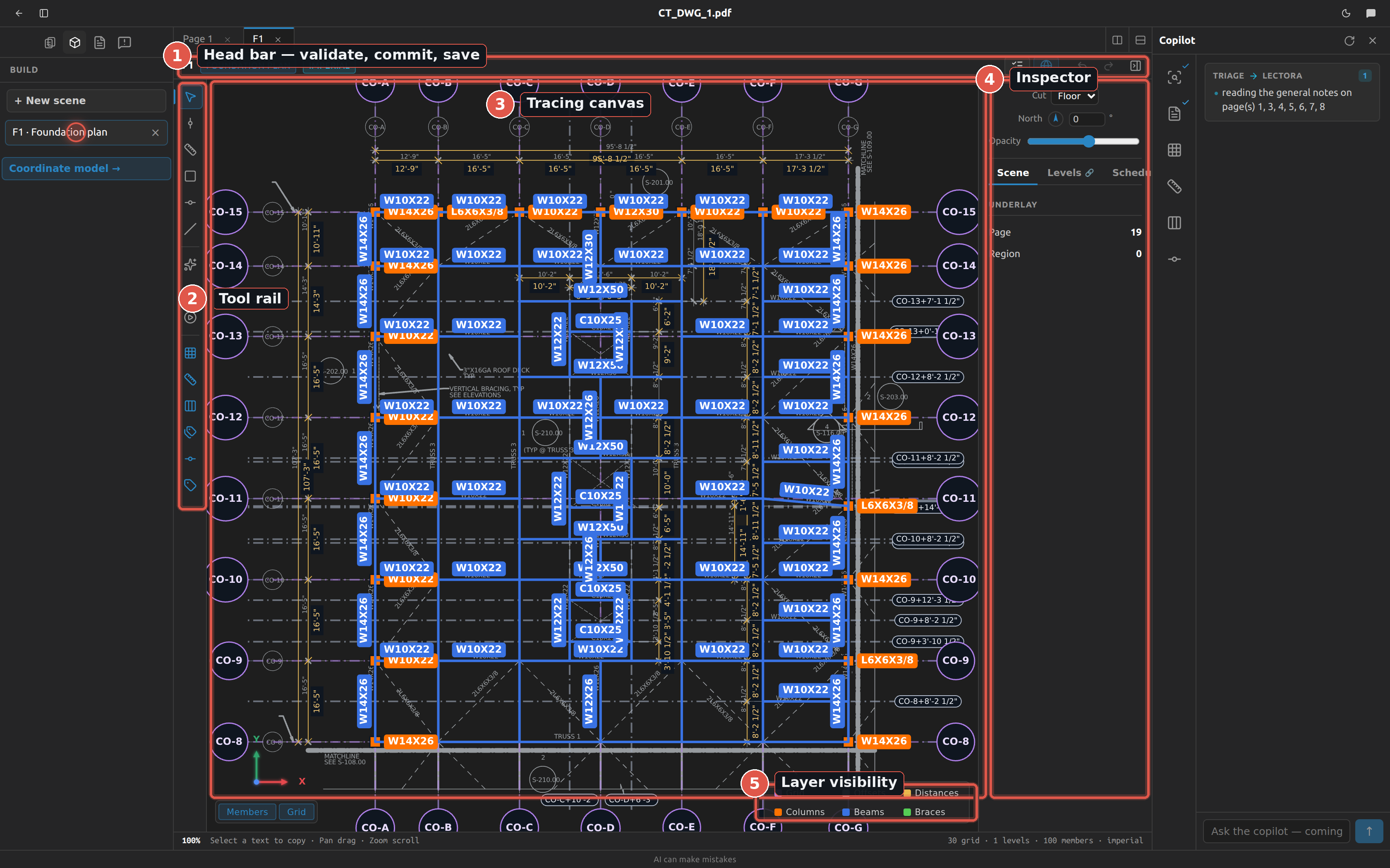
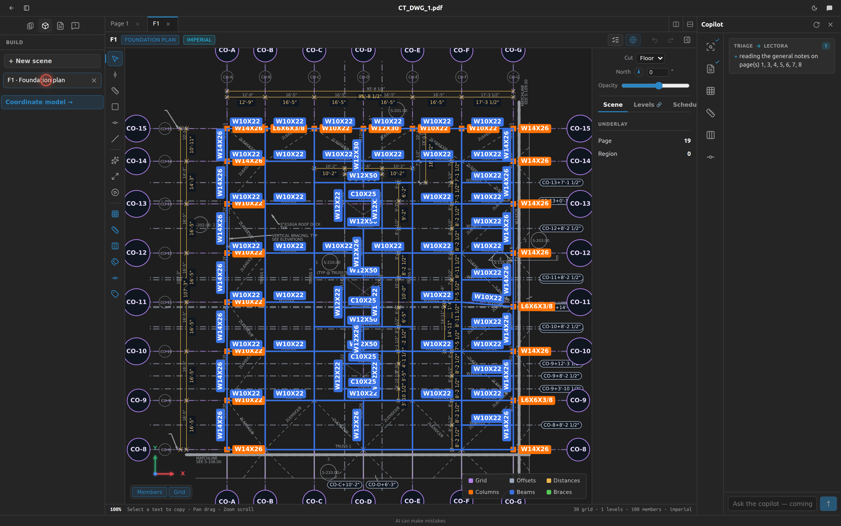
This page is the map of the editor. The tracing itself is on three pages of its own:
- Tracing a plan — grid, dimension, columns, beams, braces, slope fill.
- Tracing an elevation — levels, offset elevations, slants, the Member tool, which grids the sheet runs along.
- AI detection — the detect steps, prefill from the building, review.
Create a scene
- Open the Build panel in the sidebar and click
+ New scene. Or, on a converted page, right-click a region in the Regions tool and chooseBuild scene from this region— that fills the page and region in for you. - Type a Name.
- Choose the View type —
Plan,ElevationorDelegated design. - Choose the Page, then the Region on it.
- For a plan only, choose the Level it cuts.
- Click Create.
The New scene dialog, field by field
| Field | What it holds | When it appears |
|---|---|---|
| Name | Free text, placeholder e.g. Level 2 Framing. Focused when the dialog opens. | Always |
| View type | Plan, Elevation or Delegated design. Defaults to Plan. | Always |
| Source | Read-only, reads Page 4 · Region 2. | Only when you came from Build scene from this region — the Page and Region pickers are hidden |
| Page | Select, opens on Choose a page…. Rows read Page 4, plus the sheet number when known. | Unless a source is preset |
| Region | Select, opens on Choose a region…. Auto-picked when the page has exactly one. Shows Loading regions… while it fetches. | Once a page is chosen |
| Level | Select of the project's levels as Level 2 · 24'-6", plus New level… at the bottom. | Plan only |
| Level name | Placeholder e.g. Level 2. | Only after choosing New level… |
| Elevation | Placeholder e.g. 24'-6" or 24.5. | Only after choosing New level… |
| Foundation plan | Checkbox, off by default: the level is the base of the steel. | Plan only |
The Z arm — seeing under the floor
With the Model chip on, the axis gizmo in the corner of the canvas grows a third, dashed Z arm. Drag it and the model shows further past this sheet's level — down to the floor below, and no further. Let it go back to nothing and you see this floor's own storey, which is what the sheet is about.
The arm's length is the setting, so the gizmo tells you where you are without a readout. On a foundation plan it works the other way up: it looks upward, through the storey the columns rise into.
The pull is remembered and shared across sheets — half way is half way, whatever the storey height happens to be on each one.
Foundation plan — what the level means
A level is one elevation, and two kinds of plan mean opposite things by it.
- On a framing or roof plan, the level is the top of steel — where the beams finish. Leave the box off; this is the ordinary case.
- On a column and base plate plan, or a foundation plan, the level is the base of the steel — where the columns start and rise from. Tick the box.
Nobody can work this out from the sheet name reliably, so Fablnx asks instead of guessing. Tick it wrong and you can change it later — it is not baked into the scene.
If the page has no regions, the picker says No regions yet — open the page and use the Regions tool to segment it first. Go and segment the page first — a scene needs a region to sit on.
Pushing one stage at a time
Next to Push there is a chevron. It opens the four stages, in the order you would build them:
| Stage | What it writes |
|---|---|
| Grid lines & levels | The solved grid and the levels, and no steel |
| Columns | This sheet's columns |
| Beams | This sheet's beams |
| Braces | This sheet's braces |
A stage waits for the one before it — a beam frames into a column, and writing it before the column is writing it onto nothing. Anything you cannot push yet says why: push the grid first. A stage with nothing in it says nothing left to push and does not hold up the ones after it.
A stage is only stopped by questions about what it writes. Pushing the grid needs the grid to be right and nothing else — a beam with no steel grade does not hold it back. The question is still raised and still shows in the RFIs panel; it just doesn't refuse a step you couldn't fix it from.
Push itself still writes everything. The chevron is for taking one piece, not for choosing what the button already means.
Pushing a stage never removes what another stage put there, so you can go back and push the grid again after the columns without losing them.
When Create is disabled
Create is disabled until all of these are true:
| Requirement | Applies to |
|---|---|
| The Name is not blank | Plan and elevation |
| A Region is chosen (already true when you came from a region) | Plan and elevation |
A Level is chosen — or, under New level…, both a level name and an elevation Fablnx can read | Plan only |
An elevation has no last requirement: it names no grid lines at creation, so name plus region is enough. While the create is in flight the button reads Creating… and Cancel is disabled.
Why an elevation isn't asked which grids it runs along
An elevation runs along a plane perpendicular to the lines it crosses — and those lines do not exist yet, because you have not drawn this sheet's grid. So the question is asked later, in the inspector, once the grid is there and the answer can be a list of real lines rather than free text. See Tracing an elevation.
New level… is created once
If the create fails and you press Create again, the level you typed is not created a second time — Fablnx remembers the one it made. The dialog stays open on an error so you can fix and retry; it closes only on success.
Manage scenes
Scenes live in the Build panel in the sidebar.
| Action | How |
|---|---|
| Open | Click the row. It reads {name} · Plan or {name} · Elevation. |
| Rename | Click the pencil (Rename), or double-click the name. Enter commits; Esc or clicking away abandons; an empty name does nothing. |
| Delete | Click the ×, then confirm. |
| Reorder | Drag a row up or down the list. A line shows where it will land; drop it and it stays there, in every window. Plans move among plans and elevations among elevations. |
| See what is committed | A globe badge on the row, Committed to world. |
Deleting asks first, in a dialog titled Delete scene?: "Level 2 Framing" and its grid, members and markups will be removed.
With no scenes the panel reads No scenes yet. Once the project has both kinds, the list splits under Plans and Elevations headings; with only one kind it stays a single ungrouped list.
A rename lands everywhere at once — the list, the editor tab and the head bar. Nothing here needs refreshing. New scenes join the bottom of the list, and the order you set is kept.
The four parts of the screen
| Part | Where | What it is | Documented in |
|---|---|---|---|
| Head bar | Across the top | Name, view type, scale, Push to Tekla, Undo/Redo, save spinner, panel toggle | Below and Validation & the world |
| Tool rail | Down the left | The drawing tools, Fit view, Review, and the AI detect steps | Below and AI detection |
| Canvas | The middle | The drawing underlay and everything you place on it | Below |
| Inspector | Down the right | Changes with the tool: grid table, dimensions, levels, slopes, member profiles | Plans and Elevations |
A status bar runs under all four. Drag the inspector's left edge to resize it (180–560 px), or collapse it entirely with the head bar's panel toggle (Hide panel / Show panel) to give the canvas the room.
The scene toolbar
Three settings sit at the top of the inspector whenever the Select tool is active with nothing selected. They apply to the whole scene, not to a selection.
| Control | What it sets | Notes |
|---|---|---|
| Cut | Which project level this plan cuts | Tooltip Cut level (this plan's Z). Plans only — an elevation runs along grid lines instead. This is the same value the New scene dialog calls Level. |
| North | The project north angle, in degrees | A compass dial with a degrees readout. |
| Opacity | How strongly the drawing underlay shows through | A slider, 0.7 by default. Tooltip Underlay opacity. |
Two names for one setting
A plan's level is labelled Level in the New scene dialog and Cut in the editor. They are the same thing. If a tool or a detect step tells you to give this scene a level first, Cut is where you set it.
Turn the underlay down when you want to read what you have traced, and back up when you are checking it against the sheet.
Picking a tool brings the panel back to Props
A tool's own panel — its member list, what it is waiting for next — lives on the inspector's Props tab. So choosing one while a schedule or the Spec was in front brings Props back with it, the same way selecting a member does. The Run tab is the exception: a run is live output you are reading, and nothing moves you off it.
The tool rail
The rail shows six tools, and which six depends on the view type. Hover any tool for its tooltip; the shortcut is in it.
On a plan
| Tool | Tooltip | Key |
|---|---|---|
| Select | Select | V |
| Pan | Pan — drag to move the sheet | H |
| Grid line | Grid line — click a drawing line or its marker | G |
| ↳ Curved grid line | Curved grid line — click its centre, then the ring, then its name | R |
| ↳ Guide line | Guide line — two intersections; where it crosses a line is an intersection | S |
| Dimension | Dimension — two grid lines + a distance | K |
| Column | Column — one grid intersection | C |
| Beam | Beam — two grid intersections | B |
| Brace | Brace — two grid intersections | X |
On an elevation
| Tool | Tooltip | Key |
|---|---|---|
| Select | Select | V |
| Pan | Pan — drag to move the sheet | H |
| Grid line | Grid line — click a vertical the sheet crosses | G |
| Slant line | Slant line — two intersections a slope runs between | S |
| Level line | Level line — click a horizontal, or its "TOS EL" text | L |
| Dimension | Dimension — two grid lines + a distance | K |
| Member | Member — two intersections; vertical is a column, level is a beam | M |
The rows marked ↳ — on the plan table only — are under the chevron next to Grid line, not separate buttons on the rail. An elevation folds nothing: a level line is not a kind of grid line, it is the other axis of the sheet and the tool an elevation is started with, so it keeps its own button. Click the chevron to open Grid lines and pick one, or press its key — the key works whether or not the menu is open, and the menu prints it beside each name. Picking one makes it the live tool exactly as a rail button would; the Grid line button itself is unchanged and still places a straight grid line.
On screen the two columns are one string: Select (V), Grid line — click a drawing line or its marker (G). A locked tool swaps the shortcut for the reason: {tooltip} — {what's missing}.
Hover anything on the rail to watch what it does
Every tool and every detect step draws itself: rest the pointer on one and a small animation above the tooltip shows where to click and what appears. So does everything inside a chevron menu — each beam stage, each member reader, each source under Fill from the model — and each kind of dimension under the ruler. A step that is locked still shows its picture and says what is missing.
It is a diagram rather than a recording of your sheet, so it says the same thing on every drawing. It plays on a loop for as long as you hover.
Below the tools
| Button | Tooltip | Notes |
|---|---|---|
| Fit view | Fit view (F) | Fits the sheet to the canvas. Also F, or the right-click menu. |
| Review | Review detections — auto-play & verify (plan) / Review this sheet — auto-play & verify (elevation), or Resume the review at 128/412 — B·3 when this sheet was left half reviewed | Toggles the review tour. Never disabled. See AI detection. |
| AI detect | — | Seven steps on a plan, three on an elevation. See AI detection. |
Shortcuts are ignored while you type
Every editor shortcut is off while the cursor is in a text box, a number field or a dropdown, so typing a profile or a grid name never fires a tool.
Tools unlock in order
A tool you have not earned yet is greyed out and its tooltip says exactly what is missing. This is the order the work has to happen in, not a bug.
Plan
| To unlock | You need | Tooltip while locked |
|---|---|---|
| Grid line, Guide line | — always available | — |
| Dimension | At least one grid line | Dimension — two grid lines + a distance — Draw grid lines first |
| Column | At least one recorded dimension | Column — one grid intersection — Add a dimension (Calibrate) first |
| Beam | At least one column… | Beam — two grid intersections — Place columns first |
| Beam | …and a profile on every column | Beam — two grid intersections — Give every column a profile first |
| Brace | The same two conditions as Beam | Brace — two grid intersections — Place columns first / Brace — two grid intersections — Give every column a profile first |
Elevation
| To unlock | You need | Tooltip while locked |
|---|---|---|
| Grid line, Level line, Slant line | — always available | — |
| Dimension | At least one grid line | Dimension — two grid lines + a distance — Draw grid lines first |
| Member | At least one level line pinned on this sheet | Member — two intersections; vertical is a column, level is a beam — Pin a level first (Level tool, L) |
A locked tool cannot be reached by its shortcut either — the key does nothing. If the tool you are holding becomes locked (you deleted the last dimension while the Column tool was active), the editor drops you back to Select.
More reasons a control is greyed out are collected in Troubleshooting.
Click the drawing's own text
The drawing already says most of what you need to type. Whenever the tool in your hand can take a word off the sheet, every label on the drawing is outlined, the one under your cursor fills in, and the pointer turns to a hand. Click anywhere inside that box.
| Tool | What a clicked label becomes |
|---|---|
| Grid line | The line's name — a grid bubble, CO-A |
| Level line | The level, straight off TOS EL 42'-0" |
| Dimension | The bay distance, off a dimension string |
| Column / Beam / Brace / Member | The active profile, e.g. W14X26 — and it back-fills the member you just placed |
| Select, with exactly one member selected | That member's profile |
A beam call-out usually says more than the section — W14x22 (4) carries the piece count, and plenty carry a TYP as well. Click the whole label: the section is read out of it, and the member is named W14X22, spelled the way the catalog spells it.
If the label names no section at all — a dimension string, a note, a plate mark like PL1/2 — the member ends up with no profile and a message says why. Nothing is stored half-read: a profile is either one the catalog can place, or a mark your schedule defines, or nothing. So a stray click on a member that was already named clears it — click its real call-out again to put it back.
When labels stop being offered:
- Mid-span. Once the first point of a beam, brace or member is down, the snap node wins over a label. Finish or Esc the span and the outlines come back.
- With more than one member selected. There is no single member for a profile to land on, so nothing is outlined.
- With a tool that takes no labels — the labels are simply not drawn.
Why a label beats the grid when nothing is pending
Placing a member and naming it are two halves of one move: you draw the beam, then click the W14X26 written along it. Between spans there is no geometry to hit, so the label wins. Once you are mid-span the click has to mean geometry, so the node wins. The rule never changes between a plan and an elevation.
Work on the canvas
Move around
| Gesture | Result |
|---|---|
| Wheel | Zoom at the cursor, one fixed step at a time |
| Middle-drag | Pan |
| Right-drag | Pan (and no menu opens on release) |
| Space + left-drag | Pan — the trackpad fallback |
| Pan tool + left-drag | Pan |
| Left-drag with Select | Marquee box-select |
| F, the Fit view button, or Fit view on the right-click menu | Fit the sheet |
Pan is the second tool in the rail, directly under Select — it is the other thing you do with the pointer rather than something you place. Press H for it, V to go back to Select, and it is on the right-click menu with every other tool. It used to sit in the canvas corner instead; one control, one home.
The view fits itself once, when the drawing first arrives, and again if you move the scene to another page or region. After that the view is yours.
Select
- The selection switches at the bottom-left —
MembersandGrid— decide what a click or a marquee is allowed to pick. - A marquee selects every member with an endpoint inside the box.
- Clicking the same grid line, slant or level twice deselects it.
- Clicking nothing clears the selection. If there is a piece of drawing text within reach it is copied to your clipboard and the status bar flashes
Copied "W14X26".
Select a single member or dimension and a small contextual toolbar pops up at the click point with a trash button (Delete member / Delete dimension) and a button labelled Esc (Deselect).
Select more than one member and the inspector turns into a bulk bar: {n} selected, Delete {n} and Clear selection.
Find text on the sheet
With nothing selected, the Select inspector opens with a Find text box. Type into it and every matching piece of the drawing's own text lights up — a profile call-out, a mark, a note. It reports {n} match(es) highlighted on the drawing. underneath.
What you type is taken literally, so 25'-0" finds 25'-0" and you never need to think about what a quote or a slash means. Three switches sit inside the box, the same three any code editor's find bar has:
| Switch | Off | On |
|---|---|---|
| Aa Match case | typ finds TYP. | it doesn't |
| ab| Match whole word | W12 finds W12X40 | it doesn't — only W12 on its own |
| .* Use regular expression | your text is literal | your text is a pattern |
It starts empty with every switch off, unlike the Calibrate tool's box, which arrives holding the pattern for a dimension string with .* already on. The two are separate searches: switching tools does not carry one into the other, and each remembers its own text and its own switches.
A pattern that isn't valid simply highlights nothing — half-typed regexes are invalid on the way to being valid, so there is no error to dismiss.
The highlights stay on while you pick members, even though picking one swaps the box out for that member's properties. That is what the search is for under Select — find the text, then click the thing it names. Press Esc to deselect and the box comes back.
Clicking a level line does not open its panel
On an elevation, left-clicking a level line does not open its properties and does not highlight it. To delete a level line, use the bin on its row in the Level tool's Elevations list. The same applies to slant lines — use the Slant tool's Slopes list.
Right-click the canvas
The right-click menu carries, top to bottom:
Delete {label}for whatever is under the cursor —Delete column,Delete grid A,Delete dim A ↔ B.- Tools — the same six tools as the rail for this view type, with the same locks.
- AI detect — the same detect steps as the rail.
Fit view.
A right-drag pans instead and eats the menu, so you can pan with the right button freely.
Right-click Delete does not work on levels or slants
Right-click a level line or a slant line and the menu's first item reads Delete grid undefined. Clicking it deletes nothing (it does consume an undo step). Delete these from the inspector instead: the Level tool's Elevations list, or the Slant tool's Slopes list.
Snapping, and what a miss does
A column has its own circle to click
On a framed plan every column has beams landing on it, and a beam's ink runs straight through the node — so aiming at the column used to hand the click to whichever beam passed closest, and the column was only reachable in the gaps between its own connections. A column now claims a small circle of its own: inside it the click takes the column, even though a beam is nearer. Hover with Select and the circle is drawn, so you can see what the click will take before you press it. Anywhere outside it nothing has changed, and the beam is still picked as it always was.
Members always land on an intersection, never in free space — that is what lets the same member be recognised across sheets. A click has to come within roughly a finger's width of a node to take it.
| Tool | A click that misses | What you get |
|---|---|---|
| Grid line | No drawn line under the cursor | Click a drawn line to place a grid line. |
| Grid line (elevation) | A horizontal drawn line | That is a level, not a grid line — use the Level tool (L). |
| Level line | Nothing, or a line that is not horizontal | Click a horizontal drawing line — that is where a level sits. |
| Column / Beam / Brace / Member | No node — and no label either | Nothing happens |
| Slant line | No level work point | Nothing happens |
| Dimension | No grid line, with fewer than two picked | Nothing happens |
| Select | Nothing at all | The selection clears; nearby drawing text is copied |
On an elevation, hovering any node shows its elevation in feet-inches — under every tool, including Select, because reading a height is not a placement.
Move a member's end
- Select exactly one member. Small white square grips appear — one on a plan column, two on any span.
- Click and release a grip. Every legal target is drawn as an open blue ring, and the ring under your cursor fills in. Click a ring to move the end there.
- Or just drag the grip and let go — it takes the nearest offered ring, so a drag can never land somewhere a click could not.
- Click the grip again, or anywhere else, to disarm.
The member keeps its profile, its grade and its other end, so this is how you fix a member on the wrong bay — not by deleting and redrawing it. Fablnx will not offer the member's own other end, or a station that already holds a column.
Follow a section callout
The section and detail bubbles printed on the sheet — "3/S-301" — are drawn in the scene as well as on the page. They sit quietly: a thin outline traced round the mark itself, not a box round it, so the arrowhead on a section callout is part of what you see and part of what you can click.
Hover one and it brightens and tells you what it names. Click it and the detail it points at opens right there, in a small window over the drawing you are working on — the same preview the page viewer shows, so the gesture means one thing in both places.
Inside the preview: scroll to zoom, drag to pan, double-click to fit it again. The header names the detail and the sheet it lives on and, for a section, which way the cut looks. Close it with the X, with Esc, or by clicking away from it.
Open {sheet} · p{n} at the foot is still there when you want the sheet itself, framed on the detail. But looking is no longer the price of asking — most of the time you want to know what a reference is, not to leave the scene you are editing for it.
A missed or wrong callout can be fixed
Ask the copilot. It can look at the sheet with every callout numbered on it, add a bubble the detector missed, and take away one that is not a callout at all. Either correction stays when callouts are detected again.
Only the ones that go somewhere
A callout printed on the sheet it names — a back-reference — and one naming a sheet this set has not triaged yet are both real marks, and you will see them on the page. They are not drawn in the scene: there they would be marks that lead nowhere.
The yellow mark does not stay
Open the sheet and the detail is boxed in yellow so you can find it on a 34x22 drawing. That mark fades after five seconds — it is a pointer, not a state, and once you are looking at the detail the drawing underneath is what you came for. The same is true of the highlight a design-spec value or a search hit leaves.
Draw a guide line on a plan
A plan has somewhere to stand wherever two grid lines cross. When the steel you need lands where no two lines cross, draw a guide line through two intersections you already have, and every place it crosses another grid line becomes an intersection too. It is the plan's version of a guide slant on an elevation.
- Pick Guide line from the rail, or press S.
- Click the first intersection, then the second.
The line is drawn warm orange with a flat tag, Guide 1, Guide 2 and so on. Its crossings show as rings while you hold a placing tool, and Column, Beam and Brace snap to them like any other intersection.
- A guide line is yours: running detection or Calibrate again never removes it.
- It follows its intersections: move or re-dimension either line it was drawn through and the guide moves with them.
- It is not a grid line of the building: it is not sent to Tekla as a grid line, but the steel standing on its crossings is pushed like any other.
- Both ends must be intersections of the sheet's own grid lines, not of another guide.
- A grid line a guide was drawn through cannot be deleted while the guide stands — delete the guide first.
- Rename or delete it like any grid line — select it, then use the inspector. Deleting it removes the steel standing on its crossings.
- The
Guide lineslayer chip hides them.
See every place you can put steel
While you hold Column, Beam, Brace or Guide line, every intersection on the plan is marked with a faint ring — including the ones a guide line makes, which no drawn line shows. An elevation does the same for its stations.
The layer chips
Bottom-right of the canvas is a grid of layer chips, each a coloured dot and a label. Click one to hide that layer; it goes muted and struck through. The tooltip reads Hide Beams when on and Show Beams when off.
A plan has eleven chips:
| Row | Chips | Colour |
|---|---|---|
| 1 | Grid | violet |
| 1 | Offsets | slate |
| 1 | Distances | amber |
| 1 | Rings | teal |
| 1 | Guide lines | warm orange |
| 2 | Columns | orange |
| 2 | Beams | blue |
| 2 | Braces | green |
| 3 | Column profiles | orange |
| 3 | Beam profiles | blue |
| 3 | Brace profiles | green |
An elevation has eleven — the same nine as a plan, without Rings and Guide lines, plus:
| Chip | Colour |
|---|---|
Levels | teal |
Offset elevations | rose |
Above the chips is an All layers checkbox. Clear it and everything goes at once — the bare sheet with nothing drawn over it; tick it and every chip comes back on. It is the whole box in one click, rather than switching each chip off in turn, and it covers the chips this view has, so an elevation's Levels and a plan's Rings go with the rest. The box shows a dash while some layers are on and some are off, which is the usual state — the first click from there clears everything.
A member's line and its profile tag are separate switches. Turn Beam profiles off to check framing without a tag on every beam; turn Beams off and leave Beam profiles on to read the sections with the linework quiet. The red "no profile" ring follows the profile layer, not the line layer.
What Grid and Offsets each cover
Grid is the named lines — the ones the contract drawings letter and number, drawn violet with bubbles. Offsets is everything Fablnx named from geometry instead: station lines, faces, opening edges, drawn slate with a flat pill tag. On an elevation the vertical family and the horizontal family get different hues on purpose, so a datum is never mistaken for a grid line — and inside each family the offset is the dimmer, dashed one.
Offsets starts off. A busy foundation plan carries forty of them over a grid of eight, and what you open a sheet to read is the contract grid. Turn the chip on for the moment the stations are the point — placing a column on a face, or checking where a station landed.
A distance is hidden with the line it names. Most offsets are named by a dimension, so turning Offsets off takes those measurements with it — otherwise the number and its leader would be left pointing at nothing. A distance between two named lines is unaffected.
Hiding a member kind also drops the colour Fablnx put on the drawing's own strokes for it, so the switch visibly works on detected members too and you get the plain sheet back.
The head bar
Left to right:
| Element | What it shows |
|---|---|
| Name | The scene's name. Renaming it in the Build panel updates it here at once. |
| View badge | Plan or Elevation |
| Scale badge | imperial once the scene is calibrated, uncalibrated before. Tooltip Scale. |
| World badge | A globe and in world, only on a committed scene. Tooltip This scene's facts are committed to world. |
| Push to Tekla | See below |
| Undo | Undo (Ctrl/⌘+Z) |
| Redo | Redo (Ctrl/⌘+Shift+Z) |
| Saving spinner | Saving…, only while a save is in flight |
| Panel toggle | Hide panel / Show panel |
Checking happens when you push
There is no separate Validate button. Pushing checks the sheet — first on its own, then against every committed scene — and tells you what stopped it. A check on its own could only ever tell you what pushing is about to tell you anyway, and a pass held from a minute ago is a claim about a sheet you have since edited.
The Push button tells you where you stand:
| Icon | Tooltip | Meaning |
|---|---|---|
| Upload | Push to Tekla — write the building into the open model | Nothing outstanding from the last attempt |
| Spinner | Pushing… | Running |
| Alert + count | 3 open questions — click to view | The push was refused. Click to open the list. |
A refusal is not an error — it means the drawing has questions outstanding, which is the ordinary case. Click a finding in the RFIs panel to jump to it on the drawing, fix it, and push again. Any edit clears the count, because the answer was about the sheet as it was.
What each finding means, and how to clear it, is on Validation & the world.
Push to Tekla
Push to Tekla writes the building into the open Tekla model. One button, one direction: there is no withdraw, because nothing joins the building in the first place — every sheet you have traced is part of it. Pushing twice changes nothing.
Push is disabled until a validation pass came back clean
Its tooltip says so: Push to Tekla — validate clean first. Click Validate, clear any findings, and the tooltip becomes Push to Tekla — write the building into the open model.
The server re-validates inside the push, so a stale pass is refused rather than trusted: Push refused — this sheet has open questions, and the findings panel opens. A clean push flashes Sheet checked, followed by what the Tekla write did.
Undo, redo and autosave
| Action | Keys |
|---|---|
| Undo | ⌘/Ctrl + Z |
| Redo | ⌘/Ctrl + Shift + Z, or ⌘/Ctrl + Y |
Every edit is one undo step, and the stack holds the last 200. A new edit clears the redo stack. Both keys are ignored while you are typing in a field.
There is no Save button. Every edit saves itself: the first edit after a pause goes immediately, and a burst of edits coalesces into one save. Fablnx forces a save before it validates, before it commits, before every detect step, and when you switch scenes. If you try to close the tab with an edit still unsaved, the browser asks you to confirm.
If a save fails
Some refusals are Fablnx's problem, not yours: when your window and the server disagree about what the scene currently holds, the save is taken again against the server's copy, with your edits replayed on top. That happens by itself, once, and you see nothing but the save landing.
What is left shows a loud Not saved — {message} pill, and the message says what the server could not do — for example a grid line that still carries members. That one is about your change, so your work stays on screen and stays unsaved. Fablnx waits for your next edit rather than retrying in a loop: fix what the message names, then make one more edit — or run Validate, which forces a save — and watch the pill clear.
Closing the tab does not lose unsaved work
If a save has not landed — you went offline, or the network dropped mid-edit — Fablnx keeps the scene on this machine, not just on screen. Close the tab, quit the app, or lose power, and reopening the scene brings your work back and folds in anything that changed on the server while you were away.
You do not have to do anything to make that happen, and there is still no Save button.
Two windows on one scene
You can open the same scene twice — a second browser window, or the Tekla extension alongside the browser — and edit in both. Saves are merged, not fought over: each save carries only the fields you changed, so if you rename a beam's profile while the other window changes its grade, both stick. Detection runs count as another writer and merge the same way.
The one thing that cannot be merged is an edit to something the other window has deleted. Those changes are skipped, and the status bar says so:
2 changes skipped
Click it to see exactly what was lost — one line each, naming the member, the fields and how long ago the change that beat yours was made:
beam A/1 → B/1 — profile: a newer change to this plan beam was made elsewhere (changed 3 minutes ago)
The rest of the save lands normally. Go to the member it names and redo the field it names, then Dismiss the note — there is nothing to retry automatically, because what your change referred to has moved on.
See the model under the sheet
Top-right of the canvas is a Model chip. Turn it on and the steel the open Tekla model already holds at this sheet's cut level is drawn faintly under the drawing: columns as small open squares, beams as thin lines, braces dashed, in the same orange / blue / green as your own members. It sits under everything you have traced, so the trace always reads on top.
It is there to answer what is already modelled here while you work, instead of finding out at validation or at reconciliation. Nothing about it changes the scene — it is a reference layer, it cannot be clicked, and it is off until you ask for it. Your choice is remembered.
It is the model, not a picture of it
Fablnx does not screenshot the Tekla window. It reads the members and redraws them on your sheet, so the underlay follows your theme, stays crisp at any zoom and lines up with the drawing rather than floating over it.
Where it comes from. Fablnx places the sheet on the model through the grid — the crossings your sheet names and the model names too — using the scale and north the scene already states. One shared crossing is enough, so the underlay is available as soon as the grid and the level are detected, and it puts the steel exactly where a Push to Tekla would.
When it shows nothing, it says why. Rather than an empty canvas you get one sentence under the chip:
| What it says | What to do |
|---|---|
| It needs Fablnx running inside Tekla Structures | Open the scene from the Tekla extension — a browser has no model to read. |
| No model is open | Open the job's model in Tekla. |
| This sheet and the model name no grid crossing in common | Detect or draw the grid, and check the labels match the ones in the model. |
| This scene has no cut level | Set the scene's Cut level on the toolbar. |
| Nothing in the model stands at LEVEL 2 | The model has no steel at that storey yet — which is usually the answer you wanted. |
An elevation is not a map of a floor, so it says so and draws nothing.
Point at the same place in the model
Split this scene and the Model tab side by side — drag one tab into the other half of the workspace — and the two follow each other's pointer. Move over the plan and a blue crosshair moves in the 3D model, in the same place in the building; move over the steel there and a blue ring appears on this sheet.
Fablnx works the mapping out from the grid — the sheet's grid lines carry labels and so do the building's — so nothing has to be calibrated or typed in. A sheet that is an elevation, one whose steel sits at several elevations, or one whose grid the building does not yet know simply has no marker: a marker in the wrong place would be worse than none. See the model viewer.
The status bar
On the left, the cursor readout: the zoom percentage (100 % is the fitted view) and the cursor's x and y on the sheet, counted up from the bottom-left corner. When the pointer has been still it reads Select a text to copy · Pan drag · Zoom scroll instead. Any status flash takes over this space for two seconds.
On the right, the running counts: 12 grid · 4 levels · 87 members, with · imperial appended once the scene is calibrated. A Not saved pill or a changes skipped note appears to their left when there is one — see Undo, redo and autosave.
The "levels" count is the project's, not this sheet's
That number is how many levels the project has in its level schedule — not how many level lines are pinned on this sheet. On a plan it is not a property of the scene at all. For the lines actually on an elevation, read the Level tool's Elevations (n) heading in the inspector.
Where to go next
- Tracing a plan — grid, dimensions, columns, beams, braces.
- Tracing an elevation — levels, slants, the Member tool.
- AI detection — let the copilot take the first pass.
- Validation & the world — what is checked, and committing.
- Icon glossary — every tool-rail icon, named.
- Keyboard shortcuts — every key the editor binds.